Model 28 TTY project...If you can't find one (within reach) how about building one? ... ! |
Quick Links Page Two - Page Three - Page Four - Page Five - Page Six - Page Seven - Page Eight - |
Disassembly and cleaning Reassembly - Keyboard Transmission mount - and main shaft Signal lines - filter and piping Adjustments and alignment - It's ALIVE Detour: Parts do break sometimes Getting back on track |
 |
||
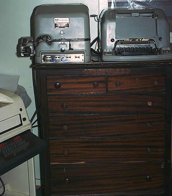
| In the early to mid 1970s - I was stationed aboard the Fleet Ballistic Submarine Tender USS PROTEUS. After an overhaul in 1972 at Mare Island, PROTEUS returned to Guam - it's home port since the mid 1960s. Since Guam is roughly 12,000 from CONUS, Sherry was allowed to accompany me to Guam - and we lived in Naval Station Guam housing. The unit we lived in had two bedrooms - so we turned the front one into a radio room / workshop. One of the things we did - was to relay MARS traffic from various points in Viet Nam and other places in the Orient - to CONUS - usually an operator in San Francisco, etc. We would copy teletype messages to tape - then re-broadcast them on. When we weren't passing traffic - the teletype gear doubled as part of our entertainment system - since we could receive all kinds of broadcasts from around the world. News was one of the main interests - and we copied UPI out of Rangoon, Reuters out of Singapore, and AP from several locations. The Kleinschmidts seen above are the TT-179 Printing Reperforator, and the TT-117 page printer. These were primarily for tape relay use. To the left is our TT-47 Model 28 Teletype. | ||
 |
||
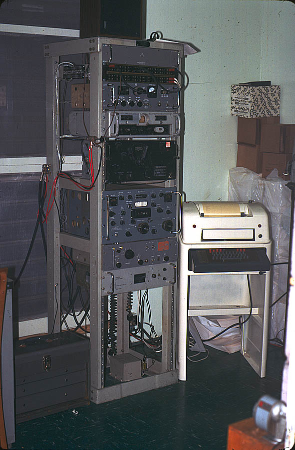
| The Model 28 next to the receiver rack. The rack contains from top to bottom: TTY loop regulator; Patch panel (both audio and TTY were "patched" from point to point here); Technical Materials TIS-3 (which converted tty digital signals and FAX analog DC signals into AFSK); URA-8A Teletype FSK converter (which converted shifted audio back into tty digital signals); BC-348 Receiver; R-391 Receiver with it's CV-591 SSB converter right below it. The power supply in the bottom of the rack is for the 391's auto tune motor. The receiver antenna select switch is on the left front of the rack; while the primary transmit/receive relay is on the left back. The transmitter is under the bench to the left. Wish we still had that "lifetime" supply of paper in the corner -- but weight was a problem returning to CONUS - and some things had to be left behind. This model 28 was near new when we got it; when we got through with it - options included a flourescent copy light, selectable unshift on space, three speed transmission - giving instant access to 60, 67 and 100 wpm; and some extra switches on the stunt box for various purposes. A few years after getting out of the service and settling down in Mississippi - a hurricane came through - and took out a radio station's building near the coast. One thing they needed was a teletype - and things being as they were - they were looking for a used one. I foolishly agreed to sell them mine - I say foolish - because it was with the "understanding" that I had the right to buy it back should they decide to get rid of it. Of course -- now it's whereabouts are not known; the people involved in the deal long gone. Model 28s are as rare as hen's teeth in these parts - with fuel prices reaching for the moon, getting a 100+ pound 28 shipped in is getting more and more impractical every day. |
||
The Project The ultimate Erector Set: build a Model 28 out of pieces / parts.
|
||
 |
||
| When this disaster showed up on ebay - the thought of building a 28 hadn't crossed my mind -- this was to be a source for spare parts - for when I did eventually find one. When I sold the 28 we had - it came complete with a spare automatic typer, original TTY Corp. manual set (operators and maintenance) ; and about 70 pounds of spare parts still in their original packing. So I thought this would - at the very least - provide some parts against a rainy day. After all - while not as hard to ship - parts are also getting harder to find. | ||
 |
||
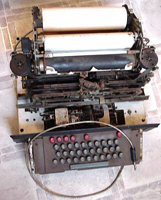
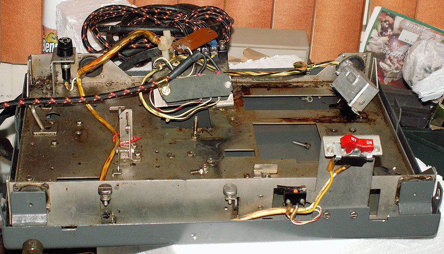
| Besides missing a (not a few) parts - including virtually all wiring, the rust and crud was everywhere. | ||
 |
||
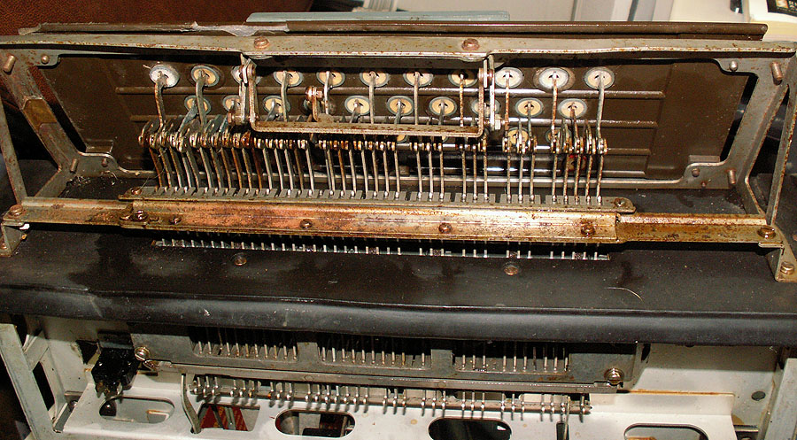
| Well - at least the keyboard seems to be "all there". That's good. | ||
 |
||
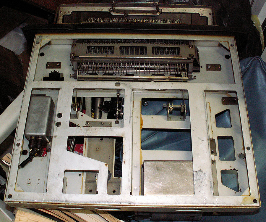
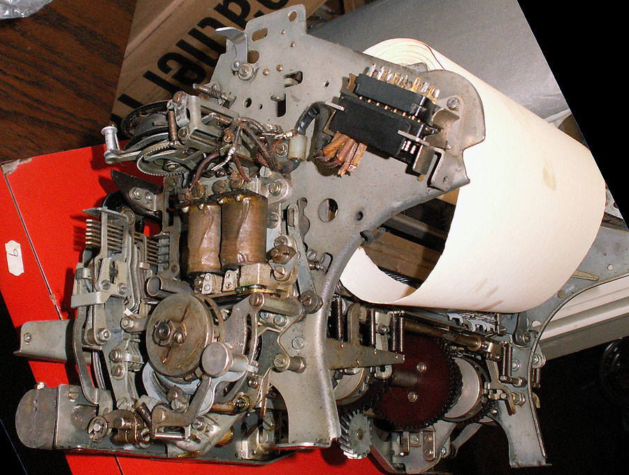
| The automatic typer, on the other hand - well parts is about it's good for. Note this is the "original" version of the autotyper - most identifiable thing is the lock-screw adjustment arm for the ranging mechanism - which was later replaced by a much more convenient ranging adjust knob. The selector magnet assembly is also "old style". | ||
 |
||
| Along comes a Klein... I had put the word out that I was looking for a teletype - sure Model 28 was mentioned - but to most people - a teletype is a teletype... So a friend offered me a TT-98B that he had gotten from the FAA here in Meridian many years ago - that was in need of "a little work". Wanting a 28 - I didn't want it myself - and I even posted a noted about it on one of the "TTY" oriented "reflector" groups I belong to (GreenKeys) - but there was no interest there at the time either. After many months of not finding a 28 that was close enough to go get - I decided that the Klein was better than nothing - so I brought it home. I quickly found that some of the wiring had been "altered" - so I put out a request for a wiring diagram. That caught Riceguy's attention - and he promptly proposed a trade: He had a 28 compact (standard, not Tempest) sans case - that was in pretty good shape - how about a swap? Honestly - I think he got the short end of the deal - but he assured me he likes a challenge (glutton for punishment is more like it!) - and was quite happy with the trade. | ||
 |
||
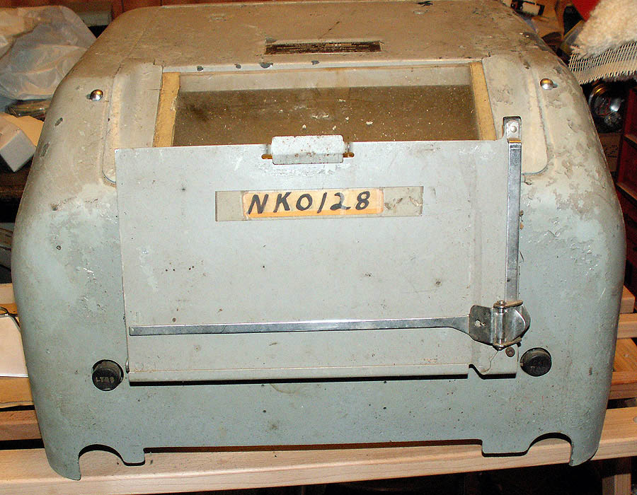
| Here's the TT-98's cover... This thing is in ROUGH shape... And what did he offer in trade? | ||
 |
||
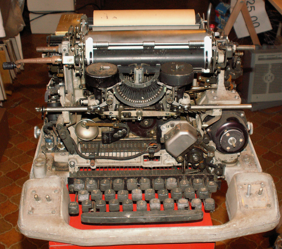
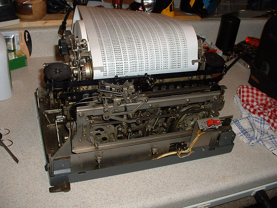
| Upon arrival - it's was a working 28 - which is what I want - he wanted the TT-98B - and he's happy. I'm delighted. Sherry isn't so sure - as within hours of arriving - that working compact looked like this: |
||
 |
||
| Goal: to eventually replace the Model 28 we had - sans perhaps some of the "sillier" stunt box stuff...
To do that - we need : A decent autotyper; a three-speed transmission; the missing parts for the keyboard (keyboard cover and connectors and associated wiring); and a motor wouldn't hurt anything - as the one on the keyboard/base is very, very stiff. |
||
 |
||
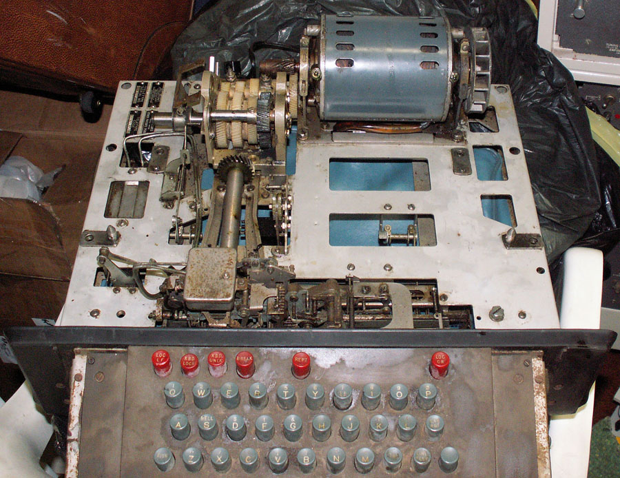
| Let's start with the keyboard / base: This original one has an intermediate gear that does three things: 1) slows the motor output speed to the correct speed for the autotyper - so that it turns the same speed as the sending device (60, 67 or 100wpm). The speed change with this setup is accomplished by changing the gear set - the one the motor shaft and the gear it drives. 2) an eccentric cam on the driven gear operates a pawl that rotates the auto-shutoff mechanism - which is the two small nylon gears just this side of the driven gear and the to the right of the keyboard drive shaft. 3) provide an "overload" clutch incase something is jammed or such - to limit damage in such a case. The intermediate gear assembly is removed and replaced by the three-speed transmission. The issues are, is that coming from a compact (where the motor is physically moved towards the outside) will the gears line up when installed on a standard base? Since the compact doesn't use an auto shutoff mechanism - is there an eccentric cam? (the third item is yes - the transmission has an overload clutch by it's very design). While measurements were encouraging - there's nothing like making sure. |
||
 |
||
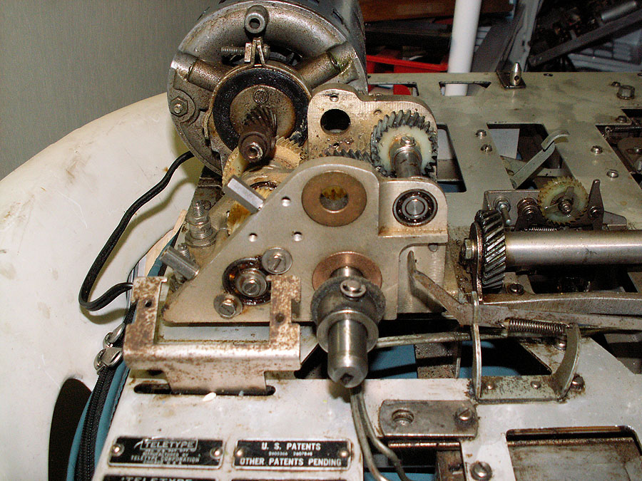
| With the intermediate gear assembly removed - the three-speed transmission is set in place. Two small issues - one is that the input gear is too low to mess properly with the motor gear - and it's also too close to the motor, almost missing the gear to the right (as viewed here). There are "elevation" adjustments on both the back and front mounting points - allowing height adjustments as needed. The motor gear that is supposed to be used with the transmission is longer - and in fact extended right to just short of the motor housing - and will match fine. As noted - the motor from the compact will be used anyway - though it's mount will have to be exchanged with this motor. The compact's start relay and capacitor mounts forward on the chassis - while the standard base's motor cap and start relay are under the motor. However - these are all small matters - and shouldn't be a problem. As can be seen (barely - but the impression is correct) there is no eccentric cam on the transmission gears are there is on the intermediate driven gear. That means some alternative method of timed turn-off will have to be made. A 555 timer IC reset by incoming line transients will serve the purpose just fine. | ||
 |
||
| In this side view of the transmission in place - the rear adjustment screws can be seen; and that almost everything clears just fine. The connector mount on the base may have to be "adjusted" away a bit; and it's also noted that there isn't any shift lever to the shift collar to provide a way to shift gears. Normally on a standard base - there is a bracket attacked to the transmission frame (the tapped holes seen here) that provides support for a lever which moves the shift collar (attaches on the stud with the "C" clip).
OK that takes care of this half of the drive train - what about the other? After all - this compact is an RO - or Read Only - which means it does not have a keyboard - so there likely isn't a keyboard drive gear on the main shaft of the autotyper... |
||
 |
||
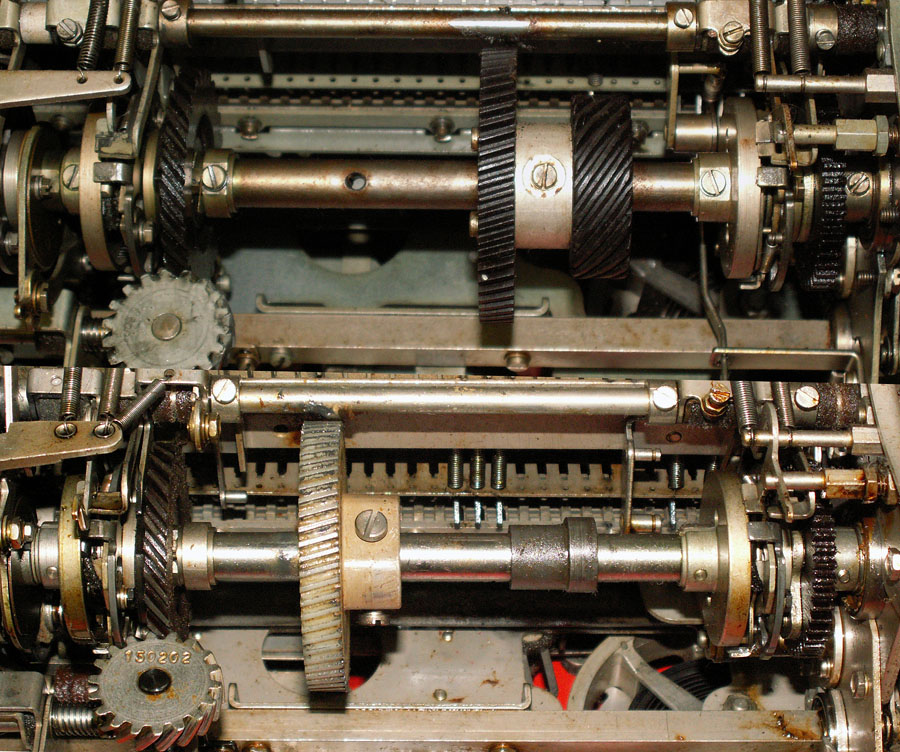
| Top picture above is the mainshaft of a "standard" autotyper - while the lower picture is the mainshaft of the autotyper out of the RO compact base. Two things are immediately noticeable: 1) the input (driven) gear on the RO is towards the left haft of the shaft and does not have a drive gear for a keyboard - while the standard Autotyper has the input (driven gear) on the right side - and does have a drive gear for a keyboard. Notice, however - that the compact RO autotyper has collar installed just about where the pair should go. Just to be sure--- | ||
 |
||
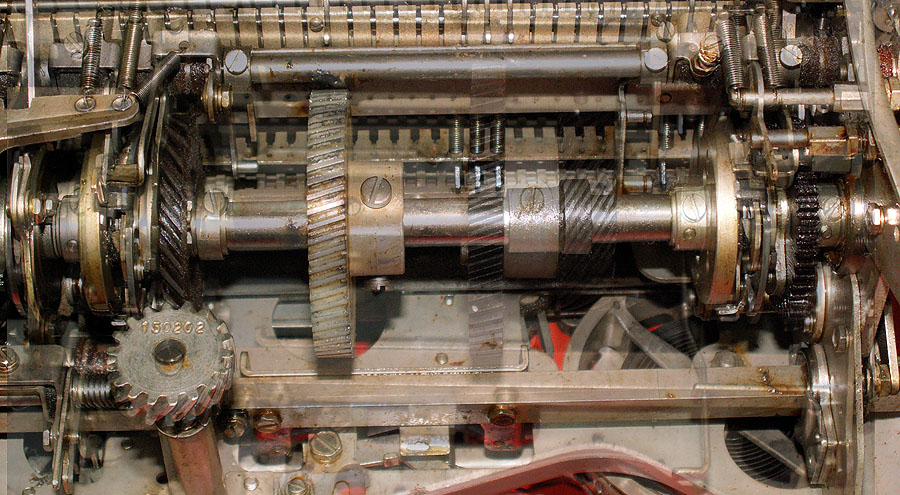
| here we've superimposed the standard shaft over the compact's shaft - and indeed we can see that the input (driven) and keyboard drive gears should replace the collar - and should be in the right place to mesh with the drive gear in the transmission. The best way to check that: | ||
 |
||
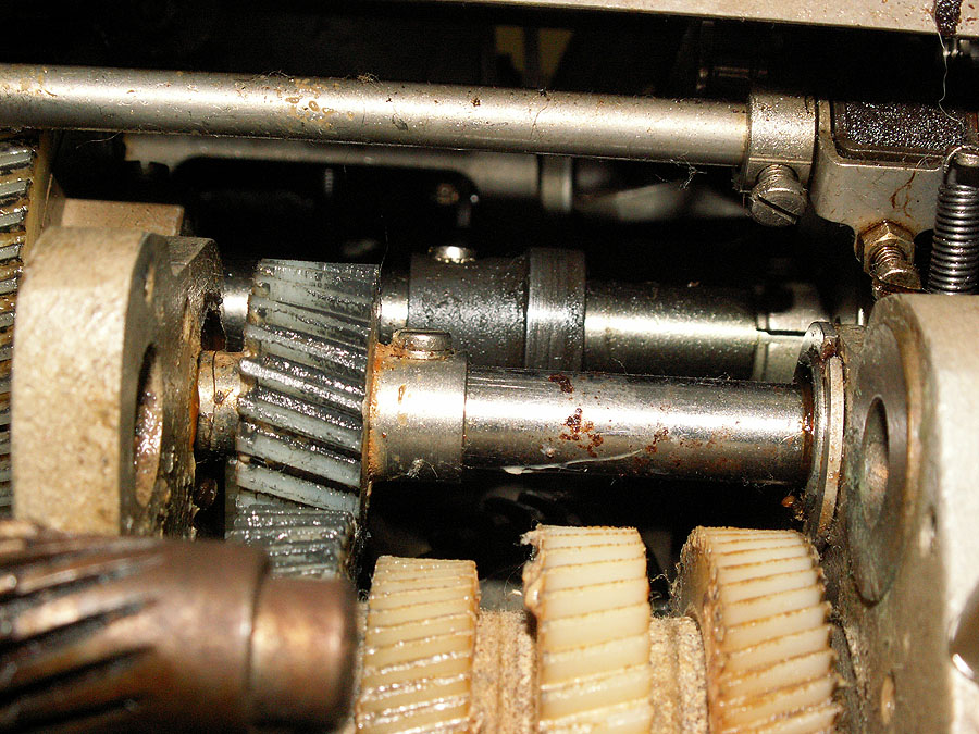
| is to put the autotyper in place and see whether the gears would indeed mesh. From this view - that does indeed appear to be the case. | ||
|
|
||
| So - now that we're pretty sure we're not on a fool's errand - the serious work will begin. | ||
 |
||
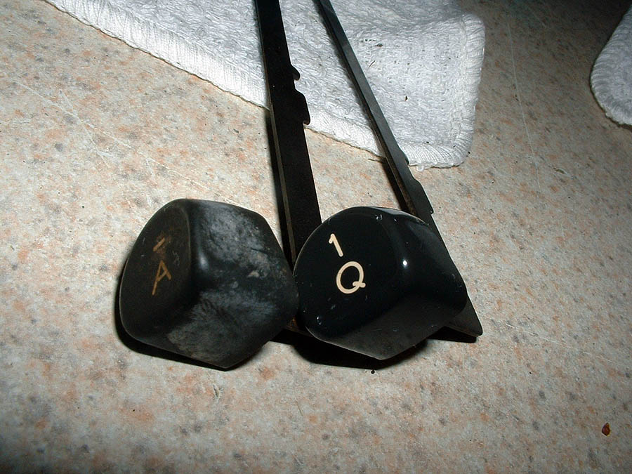
| What about Riceguy's project? - He's busy at it - as well... Within hours of him receiving it from FedEx - He sends along this "teaser" - just to let me know he's off and running... | ||
|
|
||
| Site contents copyright © 2008 Randy Guttery | ||
|
|
||
| Visitors: | ||