Model 28 TTY project...Part Five - Work (real work, what I do to pay the bills) has been just short of chaos over the past couple of weeks. That's meant no time for the project. However - it's the 4th of July weekend... and hopefully - some progress can be made in between BBQing, and other mandatory holiday activities. |
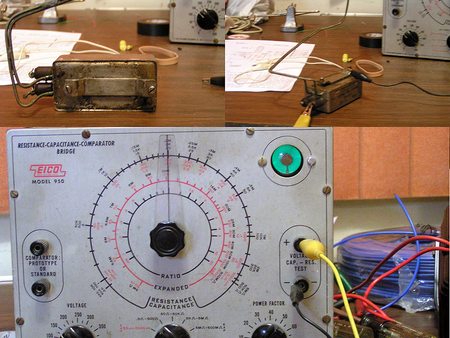 |
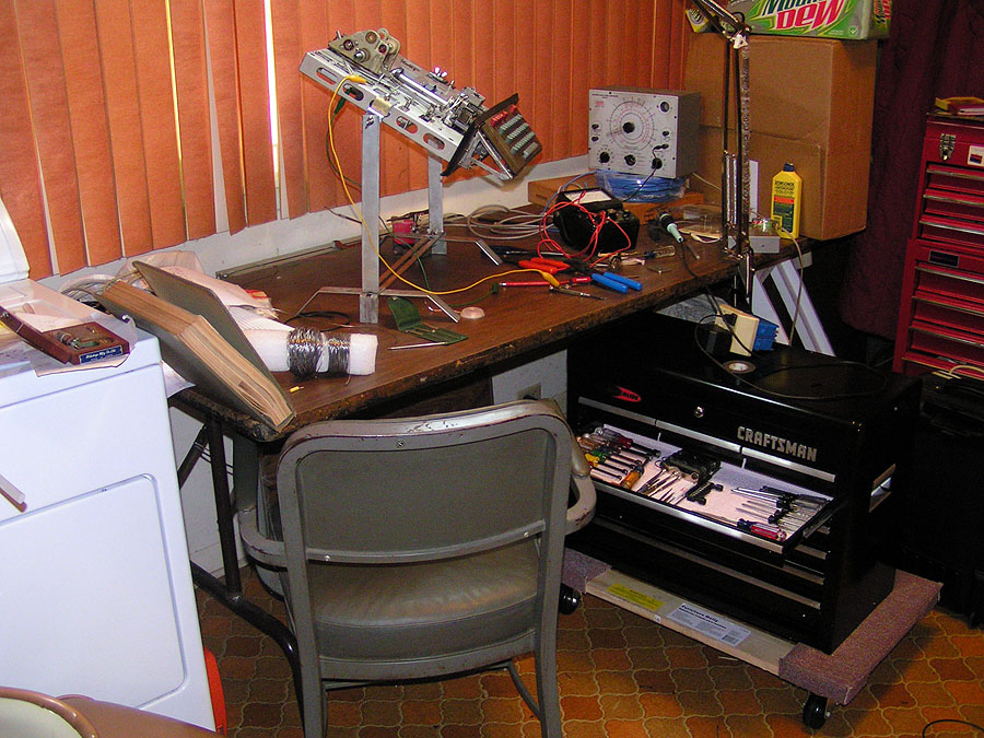
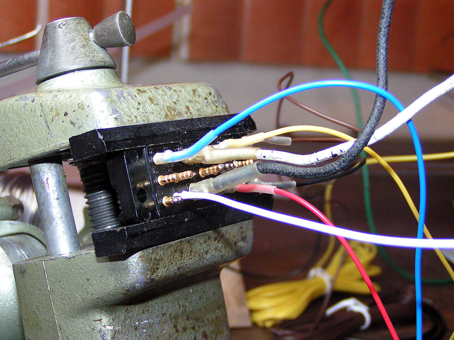
| One part of the keyboard / base assembly is the keyboard line filter. This filter is designed to keep electrical noise generated by the keyboard generator contacts from getting any further. At the time - it was well known that the "hash" that the keyboard contact generates could cause a lot of interference to radios and similar devices in the vicinity. The task of this filter is to route any high frequency noise to ground - while doing as little to the teletype signal as possible. This particular keyboard / base is a very early 1950's unit - so the parts are approaching 60 years old. The pass-through capacitors are likely ceramic - and unless damaged - are probably OK (the pass-through caps are the "post terminal" things). It's suspected that the internal capacitors are paper - and if they are - are almost certainly bad - as paper capacitors deteriorate over time - and again - these are quite old. The EICO 950 RC bridge can not only test capacitance value; it can test for leakage at actual operating voltage. A multimeter can find shorted capacitors, but isn't good at spotting capacitors that only leak significantly when under stress of actual operating voltages. The RC bridge applies high voltages and has a sensitive leakage detection circuit that spots trouble very fast. The capacitors in this filter are rated for 200WVDC - yet as can be seen - the eye is already nearly closed at less than 150 volts. Clearly there is trouble inside. |
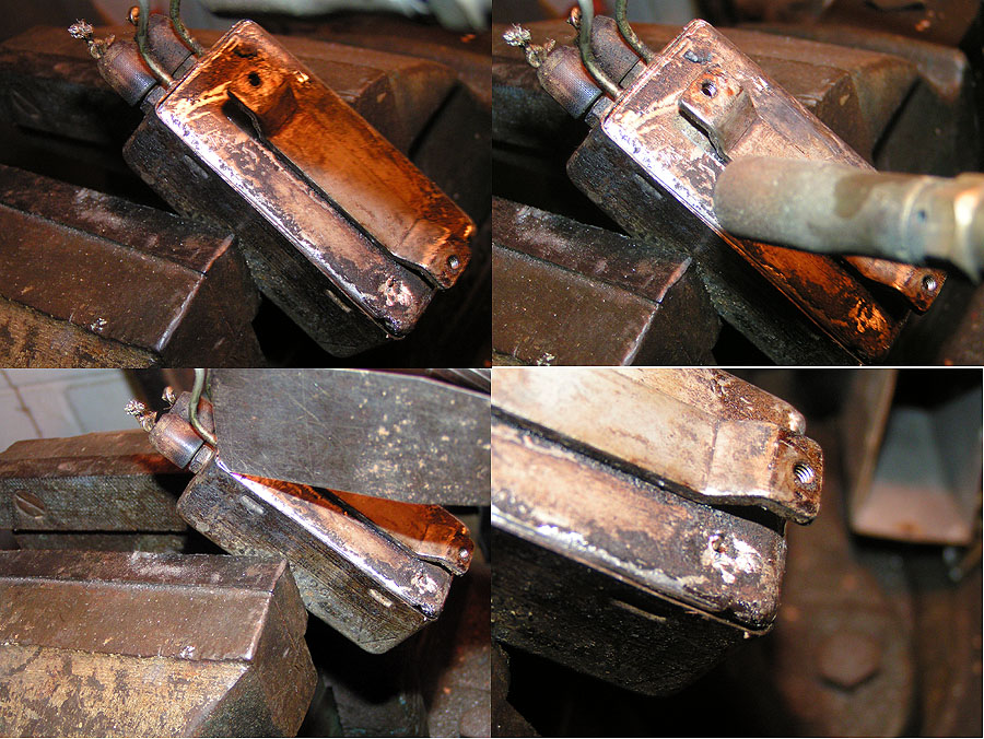 |
| Chucking the filter in a vise - a propane torch is used to gently heat the solder joint sealing the lid onto the can. A putty knife helps remove most of the solder. Note the wire sticking through the lid - this is the ground for one of the filter capacitors - and it too should be desoldered and cleaned. |
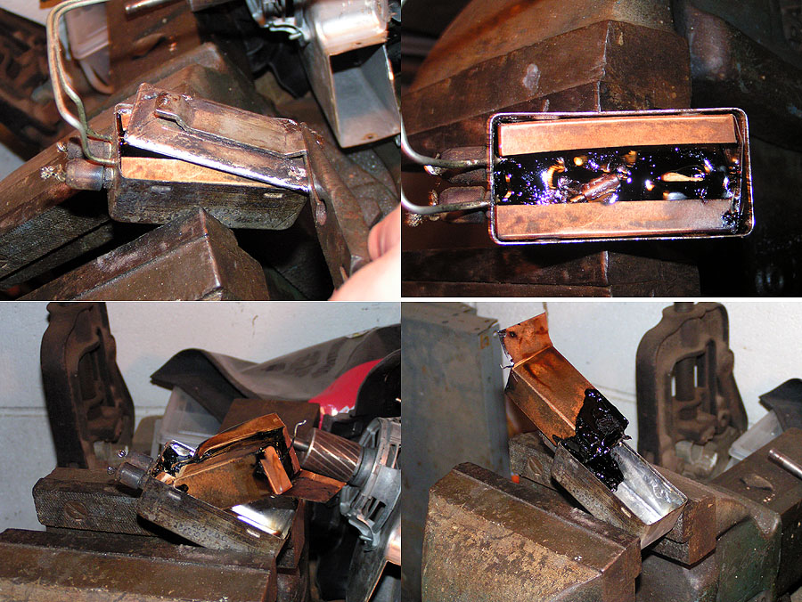 |
| The tar is heated until the whole "guts" can be lifted up and out. |
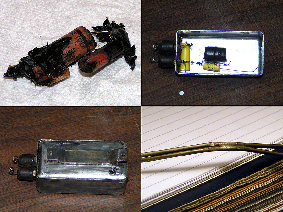 |
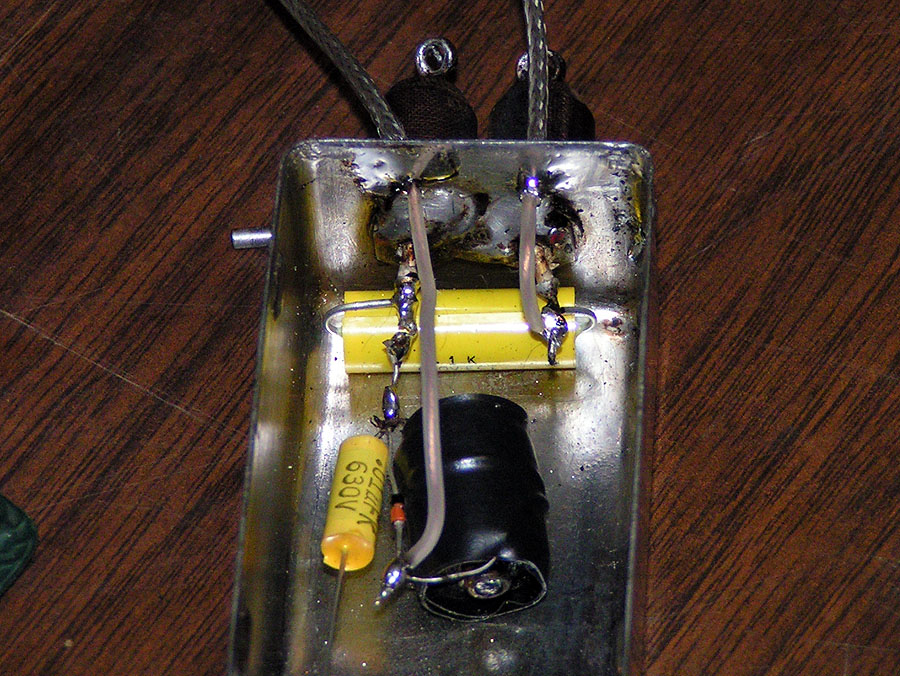
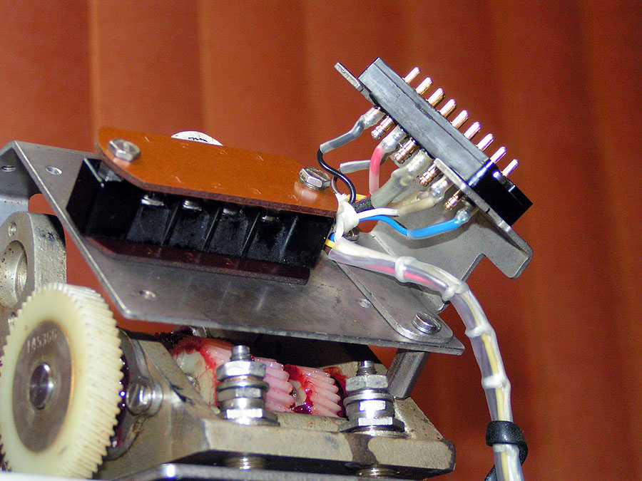
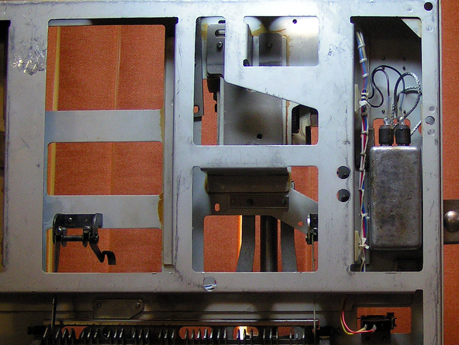
| As suspected - the internal capacitors are indeed just paper - the same as one would find in common vintage radio equipment from the era. The feed-through capacitors check out fine - the two paper caps -still warm from their "extraction" - now read nearly a dead short. The choke (coil) is OK - however - the rectifier "snubber" across it is open. Something else - while testing it was thought at first that one of the capacitors must be shorted - as the meters both indicated a short on one. However - in handling - the short would come and go - very intermittent. Close inspection of the wire "pipe" shield revealed a "crushed" area - and indeed the wire inside would occasionally short to shield pipe. So that too will have to be replaced. The top right picture shows all of the components installed back in the filter can - all that needs to be done is hooking up the shielded lines to the keyboard contact box - and soldering the "lid" back onto the can (as well as soldering the ground lead to the .01mrfd capacitor). |
 |
| Turns out - copper pipe the size and "type" used for the shield conduits is about as rare as hen's teeth - at least in these parts... 3/32nds hard-drawn copper is about as close as I could find (the measured size is .089" outside, and 068 inside diameter, if you're curious)- and of course bending that stuff is an exercise in futility. I could, I suppose - use a torch to "anneal" it - doesn't sound like much fun (since I'm somewhat clumsy with torches and such) - and I'd still have to "tin" it - sounds like a lot of work. RG-174 is just about the right size - and if I recall correctly - not that hard to "strip". So down to the local electronics supply store - (Meridian is *EXTREMELY* lucky to still have a full-service electronics store - everything from tubes to (wire) nuts!) - and get about 6 feet - a little spare "just in case". |
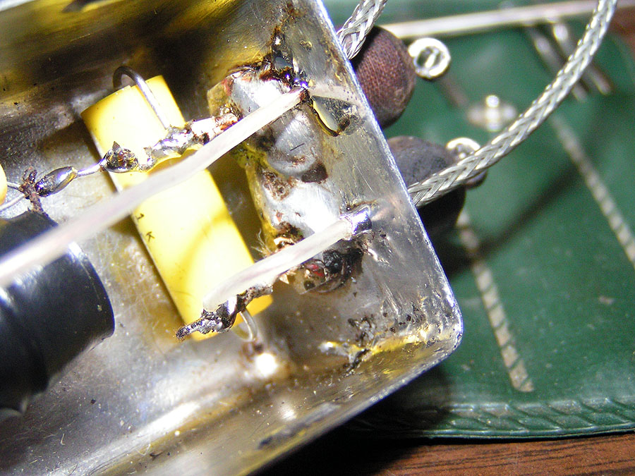 |
| As can be seen - it fits pretty well, is just about perfect size wise - and doesn't require a ton of work. And yes - the jacket comes off this length of wire simple by simply pulling it off - takes a little pulling / pushing to get it started - but then it just slides right off.
Here's how I prep the wire. First - I use regular wire strippers to remove about an inch and a half of jacket. Then I use my soldering iron to very lightly tin a small portion (say a quarter inch) of the braid about an inch from the end. This will keep the braid from fraying when I then use the wire strippers to carefully cut through the braid at the tinned spot. Gentle here - or you'll either mess up the braid - or you'll cut too deep and the insulation will from the center conductor will come off with the braid (which you really don't want to do!). Once the braid is stripped, the wire can then be inserted into the hole in the can - with just a bit of braid sticking through to the inside. Carefully flow solder around the braid and hole. Now the can be used to hold the end of the wire while you gently remove the jacket from the rest of the coax - leaving the tinned braid exposed. This puts any strain on the braid and not the center conductor or insulation. |
 |
| Here is the braid "connection" at the contact box. Again - careful with the heat so the inner insulation is not damaged. |
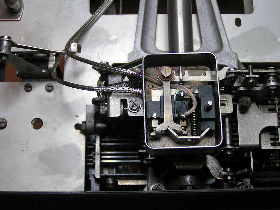 |
| As you can see - a the center conductor and insulation being in tact is very important inside the contact box - as it very tight inside. Be sure the wires are routed away from the moving parts- which is about half of everything in there... |
 |
| So - the re-built filter is back in place - still need to anchor the wire's routing - but that'll be a quick and easy task - once I find the wire hardware "bucket"... |
 |
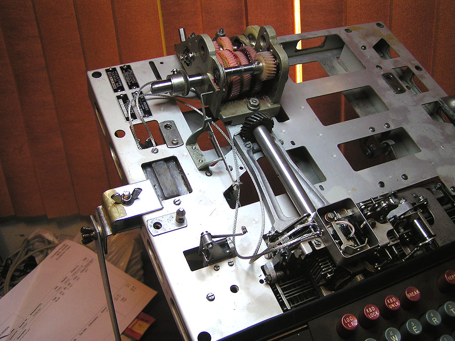
| Well - the keyboard is almost "back together"... last task: wiring - and where to put the connectors (had to be moved because of the gear-shift). |
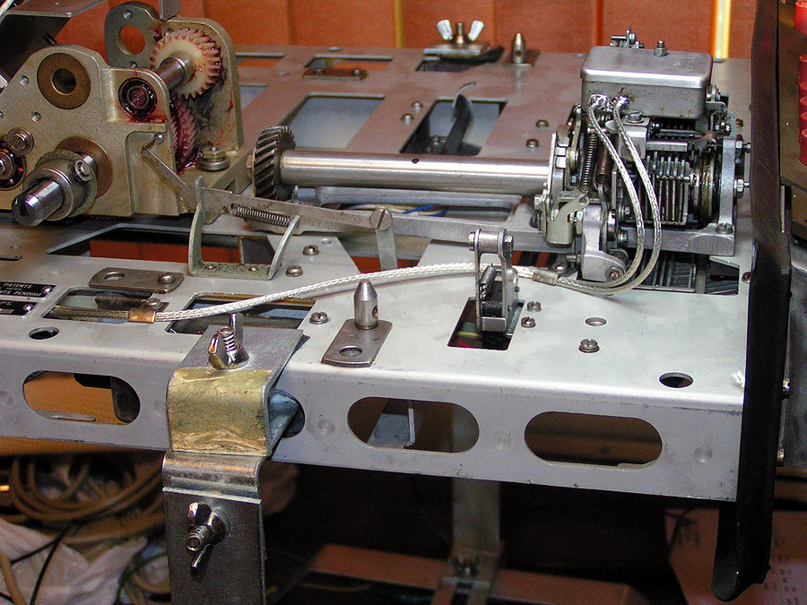 |
| Amazing what a couple of wire clamps can do. |
 |
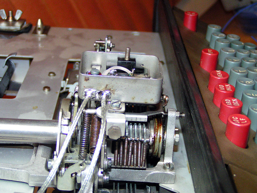
| Normally the wire "tubes" are routed between the local line-feed lever and the intermediate gear - however - the transmission is a bit wider - and it's shift mechanism is right in the area where the tubes normally cross over to the filter unit. Since the coax isn't as stiff - and not as "abuse" resistant as the copper tubing it replaced - I opted to route the coax outboard of the local-line feed lever once it was passed the automatic typer's "foot". Usually the wires to the margin light switch and the auto shut-off mechanism follow the tubes - but since the coax isn't as strong - and now takes a more "circuitous" route - I decided to run the wiring underneath the chassis. |
 |
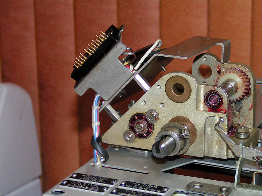
| Since the keyboard connector was missing - a new one was needed. The two 18 gauge power wires, six 22 gauge signal wires and one "jumper" were soldered to the connector. |
 |
| The connector installed in it's bracket, the two large power wires routed to the motor terminal block, |
 |
| and the signal wires laced and protected by a sheath of heatshrink tubing are routed down to under the chassis. |
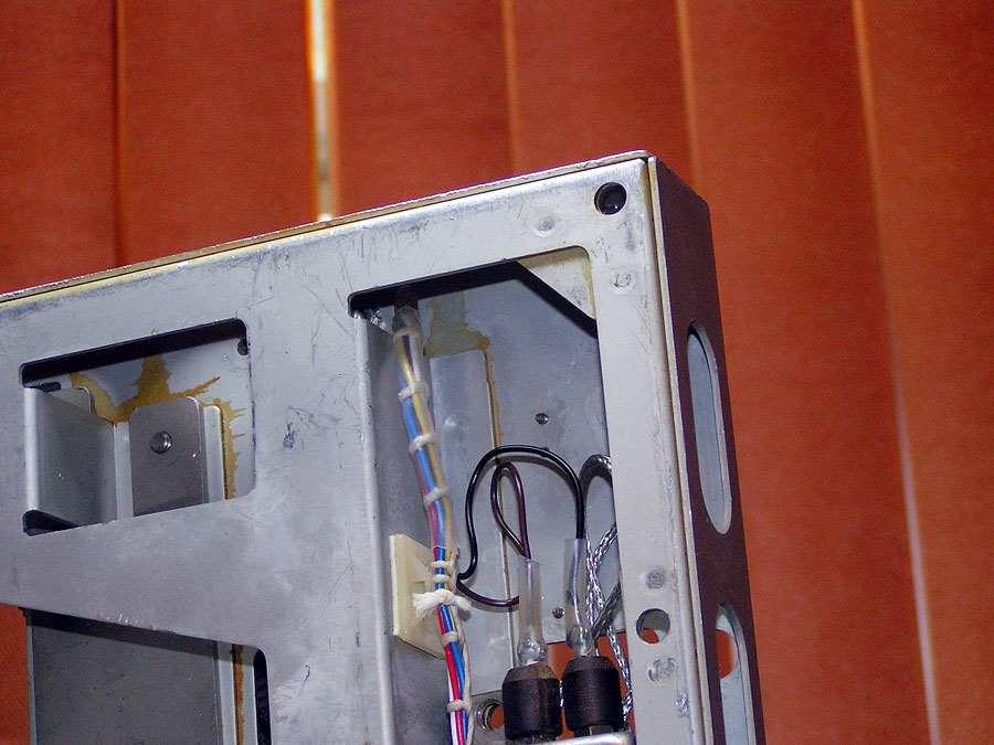 |
| connections are made to the filter unit... |
 |
| and the margin switch. Since this transmission doesn't have a cam for the auto shut-off mechanism - that assembly hasn't been re-installed. I'll have to come up with another way to accomplish auto shut-down after a length of time of inactivity. |
|
|
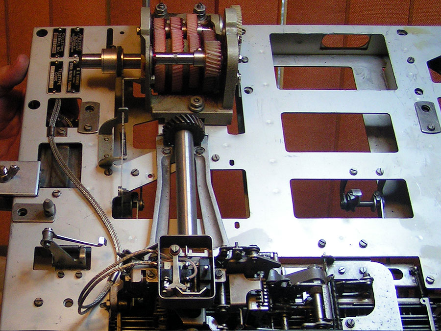
| This pretty much completes the work on the keyboard for now. Next section of the project will be to get the automatic typer back in shape. Many adjustments were "disturbed" while changing out the main driven and keyboard drive gears on the main shaft assembly. |
|
|
|
|
| Site contents copyright © 2008 Randy Guttery |
|
|