Model 28 TTY project...
|
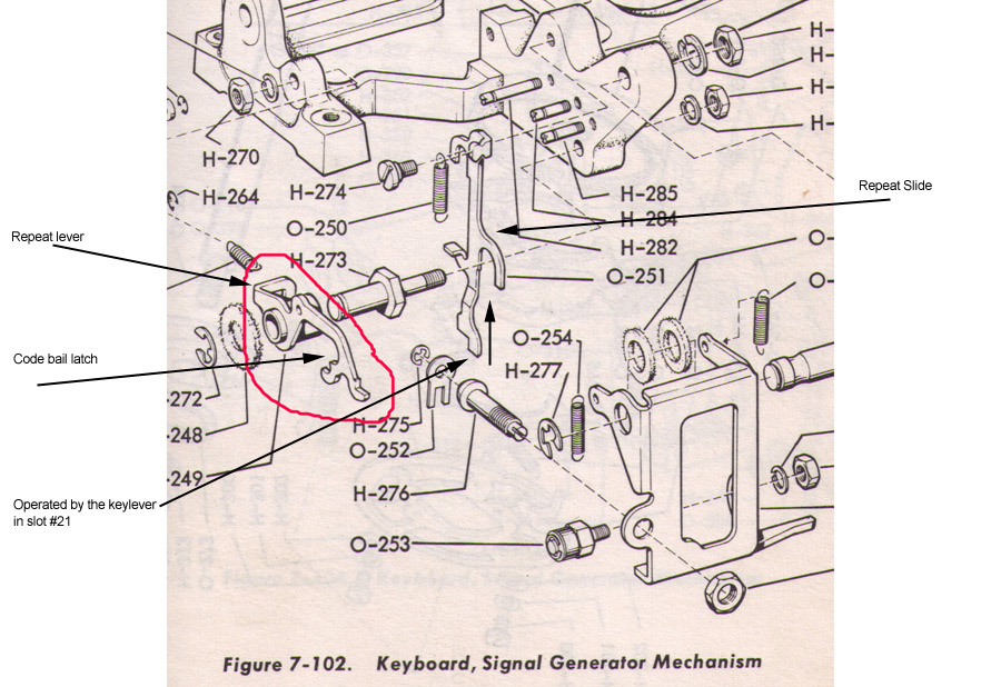 |
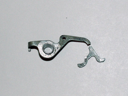
| Note both in the picture of the broken latch above - and the illustration here - there is an extension lever off the left end that is not on any of the Mk I and later keyboards. This extension is operated by the small "foot" that sticks out from the repeat slide. The repeat slide is pushed up by the keylever in slot #21. Since there is no "repeat" lever on the newer parts - one has to choose between a few options: 1) Do without the repeat function. 2) try and "jury-rig" something to transfer the slide's motion to "tripping" the bail latch. 3) change out the parts needed to accomplish the repeat function as it's implemented on the newer keyboards.
The first option is the easiest - as it requires no modifications at all - the new part with get the keyboard back in action - with little fuss, and little time. The second options is unacceptable - for obvious reasons. Option 3 is the "right" way - but there are several "issues" to be tackled: |
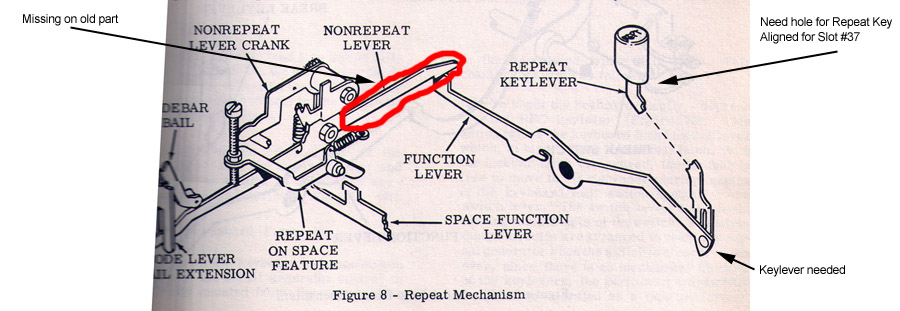 |
| The first is that the newer keyboards use a keylever to operate an "extension" on the "non-repeat" lever - keeping it from reseting the bail latch operating lever. With that lever "down" the clutch stays "tripped" - and you get repeats. The "non-repeat" lever in this keyboard does not have the extension - so it'll have to be replaced by one that does. The "non-repeat" lever - particularly the end that get's lifted by a keylever - is down near the right end of the keyboard - so there needs to be a keylever of the right type installed "down there". Fortunately slot #37 is open - and the care package has one of the "correct" type keylevers. Finally - as noted - the original "repeat" key is installed at sloth #21 - which is half-way. The new repeat key needs to be installed lined up with slot #37 - and there is no hole in the Keyguide plate at that location - so a hole will have to be drilled. |
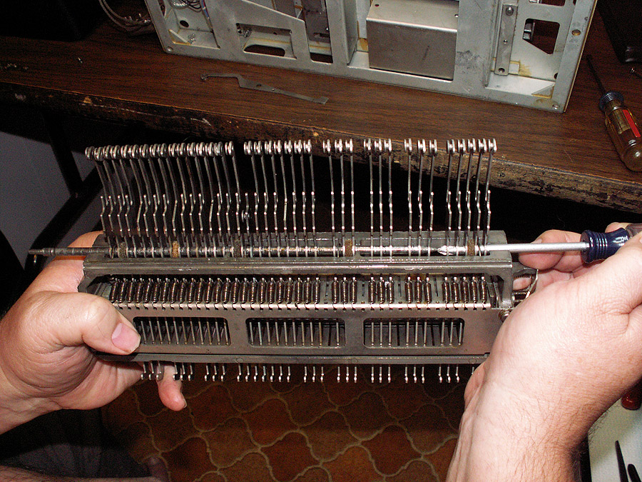 |
| Using a Don House's "tip" for changing Main Shaft components - with obvious modifications as appropriate - the keylever pivot shaft is gradually moved to the left - as a phillips screwdriver whose shaft just happens to be the right diameter chases along behind - keeping everything in place. Once the correct point is reached - |
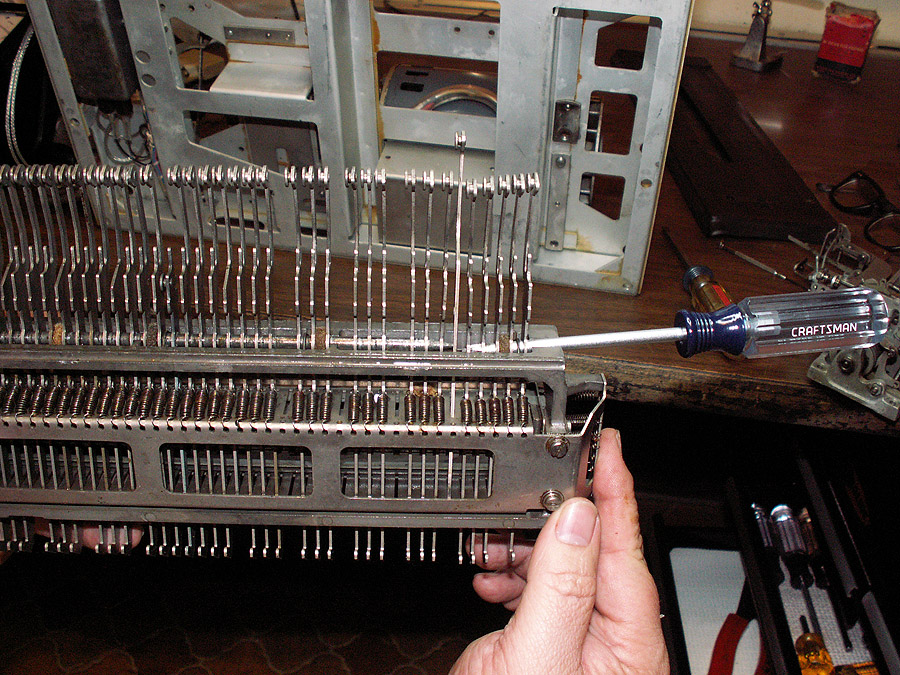 |
| Once the desired location is reached - the phillips is "backed out" just a bit, the new keylever is threaded in through the slots... |
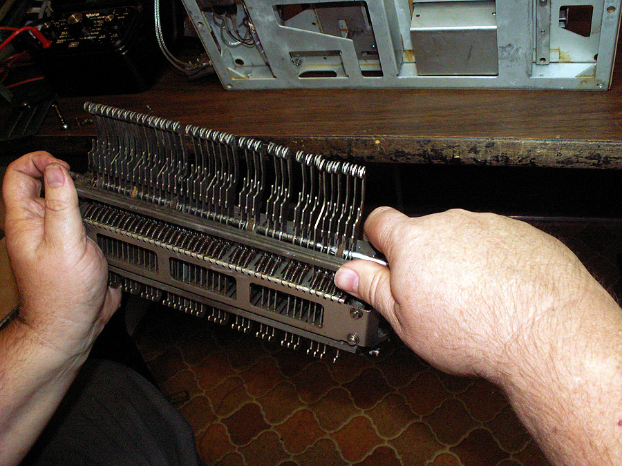 |
| then the pivot shaft "chases" the phillips back out - until it's once again in it's proper place.
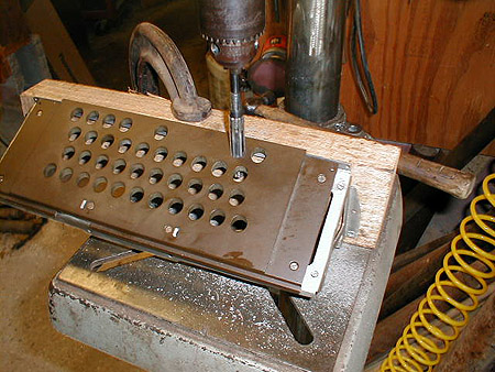
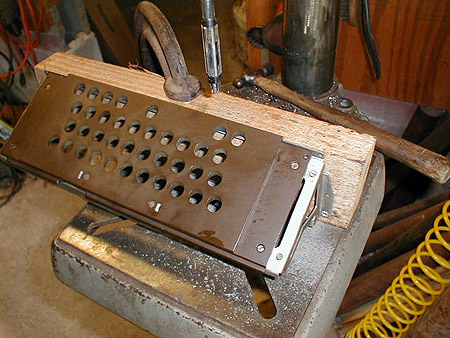
Next item: Terror on the Horizon! -- or -- How to drill a clean hole at an odd angle - without chipping or cracking -- through 50 year-old Bakelite. Well - I guess a half-inch drill bit - loaded into a hand-drill isn't the best recipe for success, huh. Even I'm not brave (dumb) enough to try that - so it's grab my drill index kit of large sizes - and see what I can do over at a friend's shop - where he has some really nice and accurate tools. Since the frame under the key guide plate has the "correct" angle - it seems like a good idea to try to use it to hold the guide plate. But since the only "plumb" face it has is the vertical face it mounts by - we need to find something to mount it to. Finding a piece of scrap 2 by 4 that's pretty square (and straight) provides the solution. Using a couple of wood screws to secure the frame to the 2X4 - and a big "C" clamp to secure the 2X4 to the drill press table gives a steady support - and more importantly - the correct drilling angle. Pretty sure this is Bakelite (or some near cousin) I'm advised to start a 1/8" inch - and work up by eighths. Doing so reduces the chance of a big drill trying to bite too aggressively and chipping an edge - and also allows for slight corrections along the way. The smaller drills - being comparatively flexible - invariably walk a slight bit down hill. Each successive size gets both "stiffer" and easier to "nudge" back on target. Finally the 1/2 inch drill did it's job (and yes - that unmistakable "smell" of Bakelite confirmed our suspicion. This is where having friends who know what they are doing and have a very well equipped shop comes in handy. I mention that that's the closest size drill I have - that the hole really needs to be a bit larger say 17/32nds - but I figure I'll have to hand ream it on out to size. |
  |
| Farrar "Hmmm..." as he pulls out a dial caliper and measured one of the original holes - then the one we're working on. "Really it's about 13.5 mm - and we're a bit under still". "You have a metric drill?" I ask. "No, something better for our purpose." at which point he pulls out this funny looking set of "somethings". "What are those?" (showing my ignorance). "Adjustable reamers". He has them from tiny little ones to big enough to ream a- well never mind - you get the idea. He gets a couple of wrenches - and adjusts the thing occasionally checking with his caliper. "We'll take this a little at a time." as he hands me the reamer. I've just pulled my drill bit out and chuck the reamer in it's place. Once again slowly carefully down through the hole - he checks with his caliper "another 8 thousandths" he mutters, adjusts the reamer and I run it through the hole once again. He checks with his caliper. "That's pretty good" he says. I note if it's tight I can probably take it on out when I polish the insides of the hole. "Huh?" he asks... "Well these holes are bearing surfaces of sorts - the keys run through them and they serve as guides as the keys slide up and down." "Oh, OK - that's easy to fix". He stops the drill press, makes one last adjustment on the reamer - then tells me to fire it up. He grabs a can of WD40 and squirts the reamer down with a heavy coat and instructs me to run it through a couple time real quick before the WD40 evaporates. I do - and when I pull the reamer out the final time - the inside surface of the hole is polished to a bright and smooth shine.
Well - I'll admit - this was one part of the project that had me way out of my "comfort zone". But thanks to Farrar - I now have a hole in the key guide plate where it needs to be for the "relocated" REPT key. The replacement code bar reset bail latch is installed - the keyboard is going back together. As noted earlier - I didn't have the spring scales when I went through the keyboard before - and sure enough - I've already found to springs WAY out of tolerance. The spring on the Keyboard clutch stop lever was WAY too strong - which explained why the clutch bar was sometimes having trouble - particularly when the unit was in repeat - where the clutch bar was just cycling (rather than "smacking") the clutch release lever. The other problem is the spring on the Lever that operates the code bar reset bail latch... it's weak - it's supposed to be 6 to 6 1/2 ounces - it's 5 1/2. And sometimes it's just not enough to push the bail latch off the roller. Replaced those - and the keyboard is more "stable" than it's ever been since I started. |
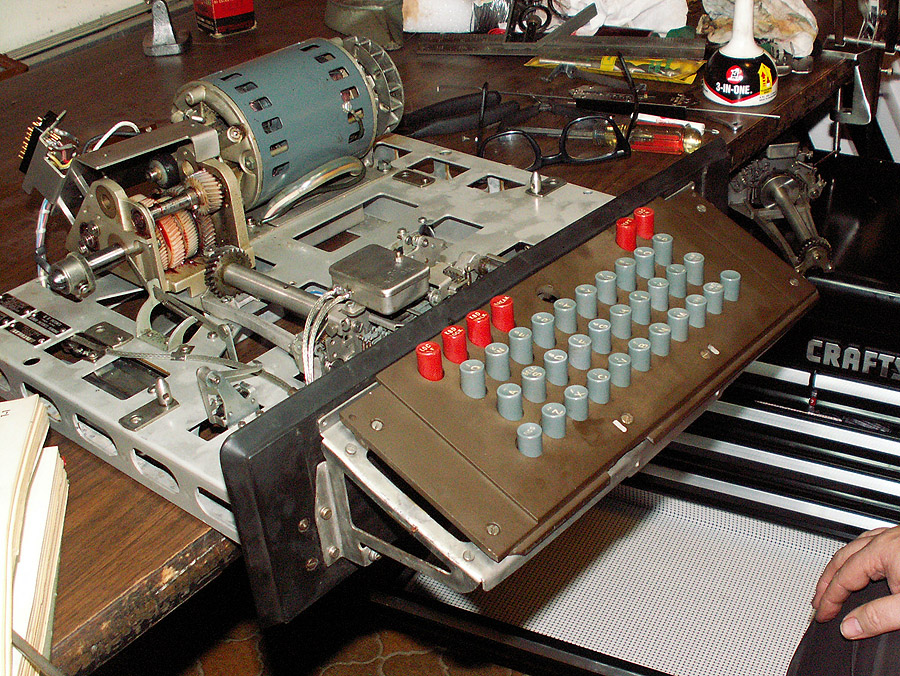 |
| With the keyboard mechanism working pretty well, the key lever frame assembly is reinstalled and all the keys put back in - except the space bar - which still has some work to be done on it's assembly. The repeat key works as it should in it's new location, though it's old location is a gaping hole just begging for a local letters switch and key. Notice the open and now empty drawer. This is something I'd always wanted. That probably sounds funny - but let me explain what it's for - during this project there were a lot of parts that had to be removed - and that empty drawer was plenty big enough not only hold all of them - but hold them grouped together with associated mounting hardware, etc. making it fast and easy to take apart and put back together. While other "stuff" was being worked on - the drawer was closed - no parts lost, etc. The upper right small drawer is also a "parts holding bin" - and that's where the space bar and it's "stuff" is at the moment. It may be an extravagance - but it's one I'm liking a lot. The generator on top of the chest is the "donor" unit the repair parts came from - it's on it's way to a permanent storage bin.
This has been an "interesting" detour - I like to think this is a lot like some of the "issues" the repair guys in the field "back then" faced as Teletype updated their equipment, etc. Of course I'm sure Teletype supplied parts for the original units a long, long time - but still - there were probably times when it was more "time effective" to adapt whatever equipment was on site - with what spares were in the truck - than to wait for "proper parts"... Thanks to: BTW - it was from Farrar's son that I got the original TT-98 -- which had a part in launching this project - so a "thanks!" there as well. |
|
|
| So how are we doing on our "ToDo List"?
1) Figure out what to do with the transmission "shifter". Right now the shift "collar" is just spinning loose. Yeah I can reach back and shift it -- but there is no outer stop. One pull too long - and I get to reassemble the shift mechanism - that is if it's not damaged in the process. 2) Cabinet. Yeah - I saw the table-top on ebay. I'd give $200 for that cabinet shipped to my door (and they can keep the keyboard and typer). Guess I'll wind up paying at least half that to get a regular cabinet shipped in. Hopefully it'll come with a proper LESU. Riceguy is trying to talk me into making a "clear" (as in Lucite, etc.) cabinet to "show off" the 28. I'll admit - while the "idea" is tempting - I have absolutely no experience in fabricating such in plastic. I'm not even that good at polishing plastic, much less forming it into something that intricate (think see-thru table-top cabinet). 3) I think I've figured out what else is missing on this unit - I *think* the 28 we had before had a local LTRS shift key / mechanism. Have to look into that. I know the Kleinschmidts had it - it's only been 20 years since we sold the 28 - and memory ain't what it used to be, and I may be mixing that up!. At least there is a little progress on this one... Yes - our original had an electric FIGS to LTRS shift - a small solenoid mounted to "kick" the Figs/Ltrs function bar back in (which causes it to shift from Figs to Ltrs on the next operation cycle). The key top / switch can go in the hole being vacated by the repeat key - since it had to move to the right end. 4) Also progress here. Thanks to Jack Murphy for his help in figuring out the code that operate "the other two" of the three "function pawls" installed in this typer - we already knew FIGS S would operate the Bell switch pawl, now we know that FIGS BLANK operates the third one (though I don't have any idea what you'd use that for) and we know that FIGS BLANK H kicks the second pawl. So a switch mounted there will take care of Motor shut-down. Thanks to Tom Tillson - the correct switch block assembly is now in hand - and will be installed during this "repair" time... 5) As noted - the bell. I'll probably wait and see what happens with a cabinet / LESU - as the bell is usually installed "there". Along with the wiring for the shutdown switch, this is also a good time to pull the bell and change the wiring for it to standard wiring (vs. for a compact R.O.). |
|
|
|
|
| Site contents copyright © 2008 Randy Guttery |
|
|
 A few days ago - I was working at my computer in the office - when I heard: "Ting! Thunk! tinkle- tinkle, tink" from the direction of the 28. Since it hadn't been run in a couple of days - I was wondering what the heck made the noise. Looking it over- soon revealed the source of the noises... The first "ting!" was the end of the code bail latch (in the keyboard) breaking off; the thunk! was the released code bail smacking it's stop (not to mention the clutch trip, etc.); the "tinkle- tinkle, tink" was the end of the code bail latch bouncing down through the codebars and other parts - finally coming to a rest on the table. As noted earlier - I'd been having "issues" with this area - I would think I would have it adjusted - only to have it mess up few days later. Turned out what was happening - was that the code bar bail latch was cracked - and slowly but surely failing. As the crack widened - it was holding the code bar bail further and further to the right - not holding the code bars far enough so that the key levers would "catch" on the edge of the teeth of the code bars. I would adjust the key frame right (which would effectively move the key levers "right" allowing them to miss the "teeth"... But then the latch would give a little more - the bail wouldn't hold as far left - the code bars would start interfering with the key levers - etc. Finally - the crack opened to the point that it just failed. A call went out on Greenkeys for the part - and soon a "care package" was on it's way. Riceguy (and George Hutchison) had both warned me that trying to keep a pre- MkI keyboard working was going to be a challenge - and obviously - they were right. Some of these parts are 50+ years old - and some - "just fail'. Riceguy had offered to send me a bunch of keyboard parts before - but I'd declined - as there are quite a few differences between the "pre MkI" and the Mk I and I knew that trying to mix them would cause issues. However - now I have little choice - as the code bail latch is broken, about zilch chance of a successful repair - so any fix - including whatever "adaptions" / "conversions", etc. to use a Mk I part is the only practical path left. So what's involved?