Sherry and Randy's Vintage Test EquipmentThis page is under construction - and probably will be for a long time...Last update - 6/12/2010 |
||||||||
|
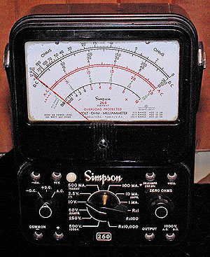
There are probably as many reasons to collect things - as there are people collecting them. For most people and most collections - collecting is a conscious effort - they like some particular object - and acquire more examples of that object as time goes by. Some times, though - people wind up with a collection without making a conscious effort - often as an extension of - or items associated with a collection they already have. So it is with our test equipment collection. As a broadcast engineer who occasionally moonlights on broadcast transmitters, etc. - I need proper equipment to troubleshoot and repair such equipment. "Guessing" at the frequency of a commercial broadcast transmitter is simply not good enough (FCC limits for an AM broadcast transmitter is 20Hz). Specialized and accurate test equipment insures that the job I do is a quality job and meets all requirements of the law - and -- that I'm efficient enough to make a little money in the process. As radio collectors - Sherry and I both use test equipment to repair and maintain the radios in our collection. While a lot of collectibles are strictly "for display" - for most of us - a radio was made to play - and play it will - no "shelf queens" here. An additional motivation towards quality and accuracy is that some of our radios are capable of extremely good performance - if maintained, adjusted and tuned to their peak. To accomplish that - like the work I do on transmitters - requires proper test equipment. So having "some" test equipment is one thing - but just when does "some" become "a collection"? Most people realize they have a collection of something - when they realize they are looking at acquiring something not soley because of it's intended purpose - but because of some additional characteristic that fits in with "the rest of the stuff". In our case - acquiring an additional Empire NF-105 was justified as obtaining spares for the one we have - as there are many parts in an NF-105 that are made of "unobtanium" - and true enough - it was dismantled and all it's parts stored away against some future need. However - when we got our third Simpson 260 - and all of them were restored to full working condition - well - we have a modest collection of Simpson 260s (had a 4th - but we gave it to a friend whose meter was accidently damaged). When you purchase the third and fourth Sensitive Research model THACH - because they look so impressive - (along with it's siblings like the U-88 "Universal Pollyranger", etc.) - Sure - a single THACH is a great meter to have - they do things other meters can't (or don't do well) - and that's collecting. And so we have yet another collection going... Radios, Sewing machines and sewing kits; Submarine Tender memorabilia (and stuff ""Navy" in general); hand bells - and a few vintage Sansui components... and test equipment. Just as a matter of organization - the equipment shown here is in order by the manufacturers name. We still have most all of the equipment shown here - though in a few instances we display something fairly rare that has gotten away from us... In those cases - that fact is noted. So here is some of our test equipment - |
||||||||
|
|
||||||||
| B & K | 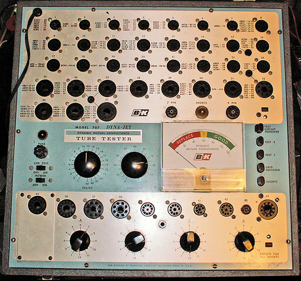 |
|||||||
|
DynaJet 707 Tube tester Basic tester with two sections - the top section is set up requiring nothing more than setting the filament voltage- the "sensitivity control" and plugging in the tube to the socket as printed on the panel. This make testing many common tubes fast and easy. The lower section can be set to test most any receiving and similar tube - simply by setting the selector dials as directed in the settings booklet. While not a particularly great tube tester - it makes sorting tubes and culling dead tubes fast and easy. |
||||||||
|
|
||||||||
|
EICO
The second piece of test equipment I ever owned was an EICO 460 O'scope- I managed to save up enough money to buy it from a neighbor whose health was failing and was disposing of his HAM equipment. Like HeathKit - EICO took much of the "sting" out of buying test equipment by assembling a kit that cost much less than any commercial equipment - yet was quite serviceable. |
||||||||
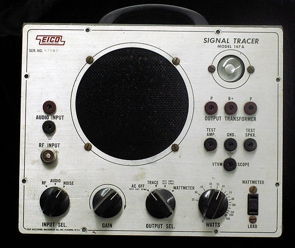 |
Eico 147A Signal Tracer with watt meter. - As Acquired | |||||||
 |
||||||||
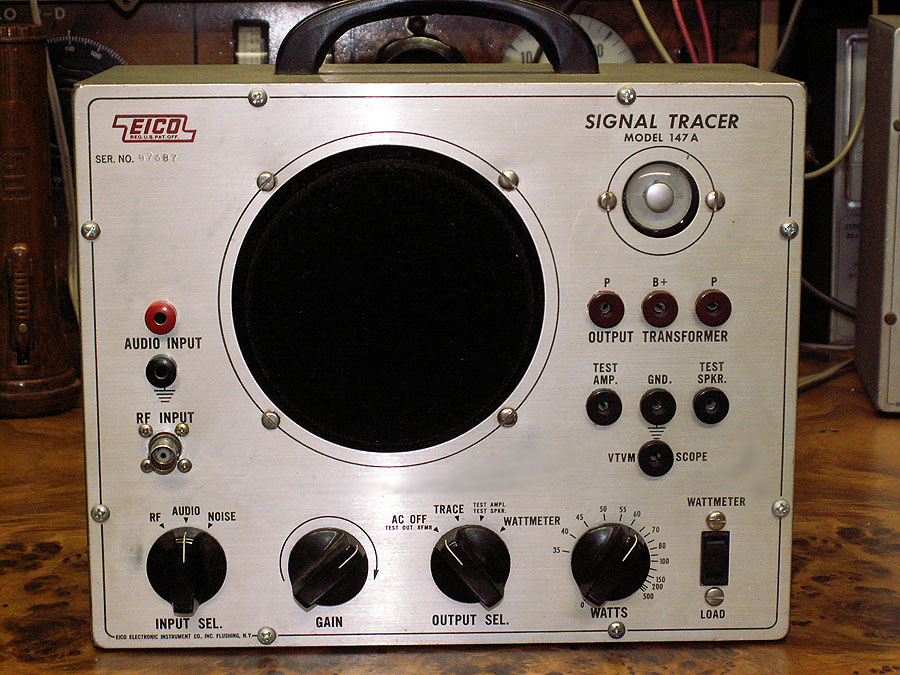
| 147A Signal Tracer after repairs. Since this is a working unit - (as opposed to a "restored museum piece") - function wins over esthetics every time. The front panel here was in quite good shape - so a good cleaning and a new set of screws - including replacing the remaining rusty screws takes care of that. The (now) obsolete Amphenol Microphone connector used for RF input has been replaced with a much more practical BNC connector. The pin-jacks used for audio input have been replaced with the now much more common Banana Jacks. Since the remaining pin jacks are seldom used - they remain original. Flipping over the speaker "grill" provides a fresh face there while remaining authentic to the unit. | ||||||||
 |
||||||||
|
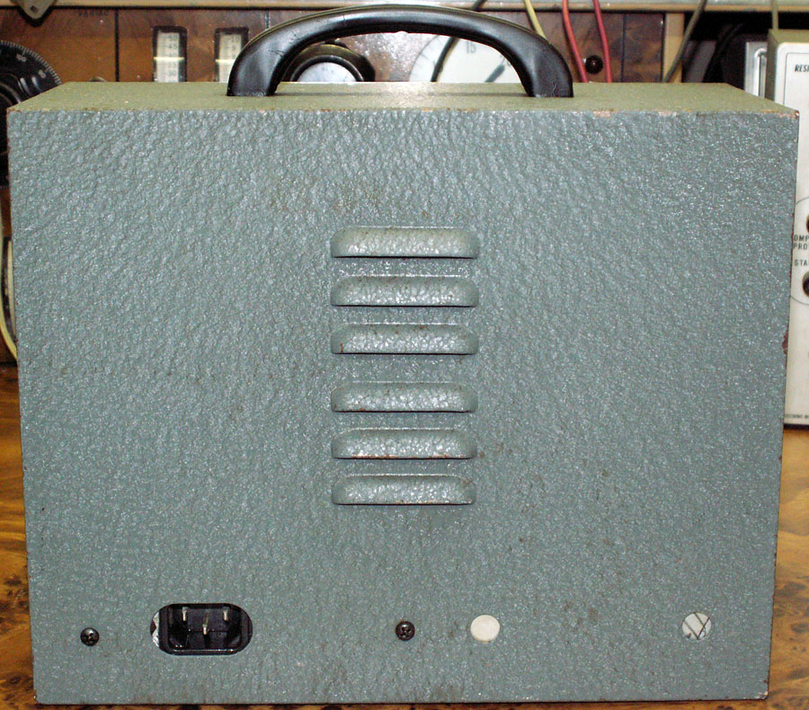
In keeping with the functional premise - the old AC cord - and it's related AC decoupling capacitor from one side of line to chassis has been replaced with a modern AC socket with built-in line filter. This assures the chassis is not "hot" with respect to ground - nor other equipment that this tester might be used with. Besides avoiding that surprising "tingle" now and then - it also reduces the likelyhood of AC hum caused by line issues.
The Eico 147A is a three-stage audio amplifier with several provisions made to make servicing radios and amplifiers easier. Each stage of the amplifier is accessible (through jacks); the output transformer and speaker are available for substitution both powered and unpowered as appropriate. The accessory RF demodulator probe allows following a signal through the RF and IF stages of a radio; direct audio input for tracing audio through various audio stages; and a "noise" mode for testing for component noise / breakdown in tube circuits. This last mode is the same as the normal Audio Trace mode - except an open circuit voltage of 130VDC (limited to 1ma) is impressed on the audio input - which is then applied to the circuit under test via the audio probe. If any component is breaking down (such as a coupling or decoupling cap, etc.) the "noise" of that failure will be audible in the Tracer's output (speaker or headphones). As noted - the 130VDC is limited by via a source resistance of approximately 130KOhm - so it doesn't present a hazzard to most tube circuitry. It is not recommended for use in semiconductor circuits as it might exceed the breakdown of some of the semiconductors. Depending on the mode switch settings - the output transformer can be driven by the Tracer's own output tube (6BQ5); or by the amplifier under test (provisions are included for push-pull outputs as well). The output from the output transformer can go either to the built-in speaker - or to drive an external speaker - in the unit under test. Likewise the speaker in the Tracer can be used as a test speaker for the unit under test. |
||||||||
|
|
||||||||
 |
||||||||
|
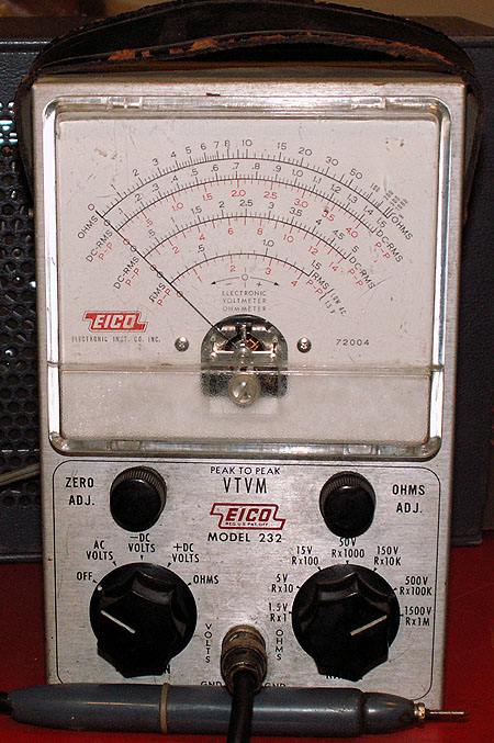
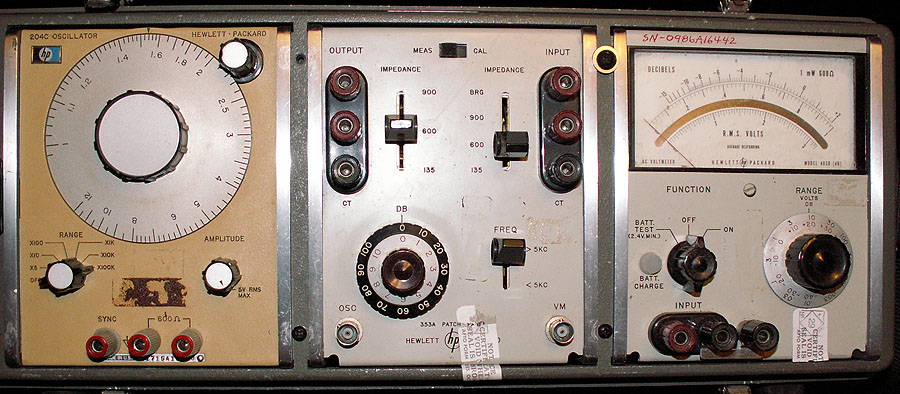
AC and DC voltage measurements from 1.5 V Full Scale to 1500V Full Scale in 7 ranges. DC input impedance is 11 Megohms all ranges. DC Isolation resistance is switch selectable in the probe. AC input impedance is 1Megohm. AC is Peak - Peak responding RMS reading 30 CPS to 30Mcps. Resistance: 1 - 1000 Megohms in seven ranges. The 4 1/2 inch meter can be set for center zero to accommodate FM Discriminator alignment. |
||||||||
|
|
||||||||
 |
||||||||
|
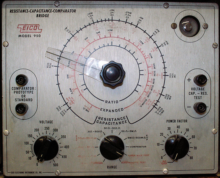
Capacity from 10pf to 5000mfd; Resistance from .5 to 500MOhm. Capacitor leakage tested in two ranges to 500VDC. Purchased new in 1973 at Radio Shack in Hawaii Like the 147A - this unit needed some repairs. In doing some testing of some high-voltage capacitors - I happened to check to be sure the unit was indeed testing caps at 250V when the control was set at 250V... It wasn't - in fact the supply for the leakage test was only about 462 volts DC - when it should be 520V. I figured the electrolytics in the power supply were failing - so checking the schematic - I picked up some replacements. Imagine my surprise when both filter caps turn out to be good. The rectifier was a 6X5 - and while it checked a bit weak - I suspected that wasn't the problem either. Doing a quick check of resistors and capacitors in that section of the tester found that the low voltage loading resistor had drifted way high - roughly twice what it should have been. It was replaced with a new 68K 1W. The tube was replaced with a 2KV .5A diode - and the high voltage supply was still measuring low - though at 502V - certainly better than it was - however - not good enough. The power supply in this unit is a bit odd - in that it develops 200V to power the eye tube - and a negative 520V to power the leakage test (capacitance, resistance and comparator circuits are powered by a separate winding on the transformer). The diode is attached at one end of the HV secondary - and oriented such that it puts out the +200V supply. The eyetube plate circuits in parallel with a low voltage bleeder resistor provides the charging current for not only the +200V supply - but also for the -520V supply capacitor on the other end of the HV winding. The Eye Tube plate current - in parallel with that 68K biasing resistor sets the balance point between the positive and negative supply (again- +200 and -520V). For whatever reason - the current drawn through the low voltage supply wasn't enough to get the negative supply up to the value needed. A little testing found that changing the bias-point resistor from 68K to 50K brought the negative supply to almost exactly -520V. The +200 sagged a bit down to 180 - but the eyetube works just fine at that voltage (the eyetube was very nearly worn out (very dim) so it had been replaced with a new one). Now everything worked as it should. Voltmeter across the capacitor terminals reads 502V with the control set at 500. Checking at other points (100, 200, 300 & 400V) shows them to be within a volt or so- plenty close for the intended purpose. Using some fresh good quality poly caps - the capacitance scales were checked at 10pfd, 100pfd, .001ufd, .01ufd, 1ufd and 10ufd. The electrolytic ranges (1, 10, 100, 1000) were checked using several good (fresh and high quality) electrolytics. Since the unit is never used with (connected to) other "plugged -in" units - and the AC cord was in good shape - it (and it's line to chassis decoupling cap) were left alone rather than replaced as was done in the 147A. The only problem with the unit is cosmetic - the red paint wasn't as good of quality as the black - and has faded and chipped off over the years. Being silk-screened on, not easy to repair - so I am looking for a better front panel. |
||||||||
|
|
||||||||
| Chatillon / Western Electric | ||||||||
 |
||||||||
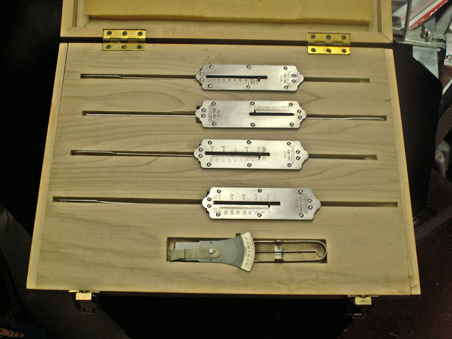
| This is the set of five standard spring scales used when working on Model 28 Teletype. The Chatillon scales range from (from top to fourth scale down) 8oz full scale; 16oz.; 32oz.; to 64oz full scale. The bottom scale is a Western Electric +/1 70gm scale - used for setting the selector magnet armature spring tension. The teletype tool set also has a complete range of round and flat gauges, and a torque screwdriver which has a 0 - 64oz-in torque range. |
||||||||
|
|
||||||||
|
Empire / Singer Metrics
|
||||||||
 |
||||||||
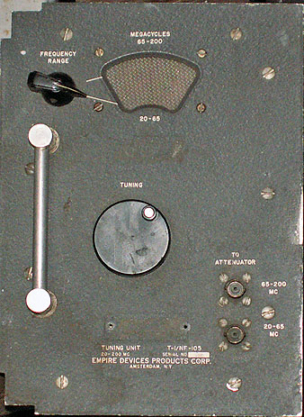
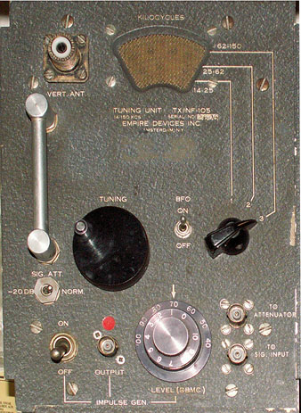
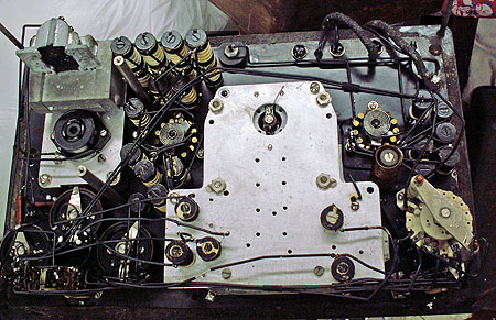
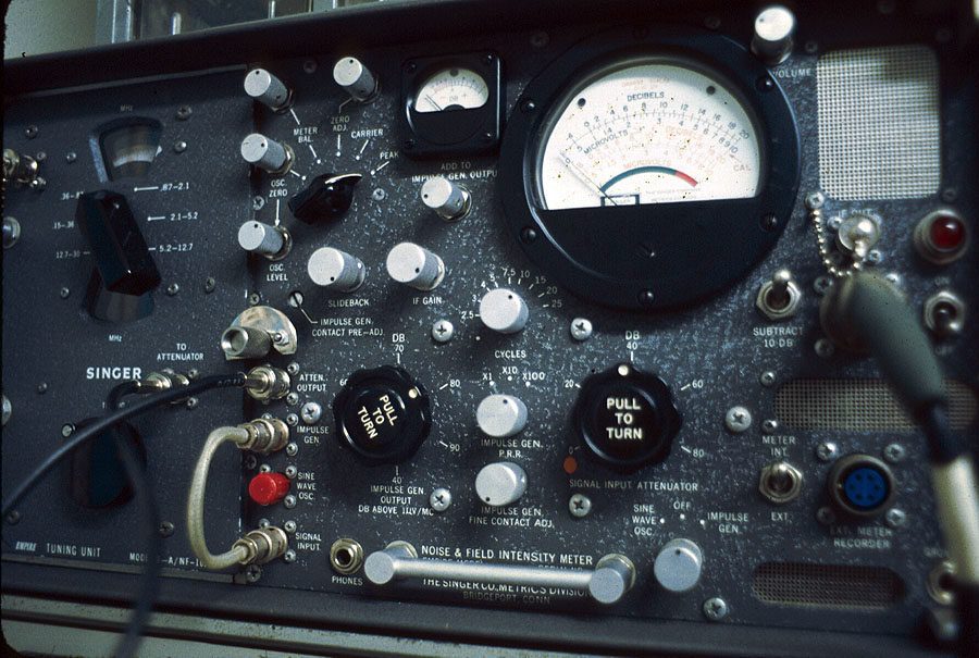
| NF-105 Noise Field Intensity Meter
In the 1950s - a need arose for a device that could detect, locate and measure interference being generated by new and increasingly (electrically) noisy devices. Stoddard and Empire were two companies that took the challenge - and a series of metering sets were developed. Along the way - it the idea of also being able to accurately plot signal strength radiated by various radiators (antenna, etc.) was included - which gave rise to ever increasing frequency capabilities. By the 1960s VLF - to below 20Kc was also recognized as a significant issue with EMI (electromagnetic interference) and those frequencies were also accommodated. One of the "products" of those efforts was the Empire NF-105. Together with it's five plug-ins - the meter is capable of accurately measuring RF from 14Kc to 1000Mc. Set up as a radio receiver - the entire unit is calibrated using either one of it's built-in signal sources - or a calibrated external reference signal. Once calibrated - the signal of interest is tuned in - and it's strength directly measured. When using one of it's probe or antennas - the signal strength in uv/m can be directly read from it's meter (and adding any attenuator settings). Since the entire signal chain (except antenna / probe) are calibrated each measurement - overall accuracy is assured. Of course today - modern Spectrum Analyzers do in seconds what it took hours to measure with these old devices. But at the time - devices like this one was the only accurate way to make such measurements Mainframe contains power supply, Sine and Impulse calibration sources, RF attenuators, and metering for both calibrators and Signal Strength. It also accommodates Mode, function and similar operator's controls. |
||||||||
|
|
||||||||
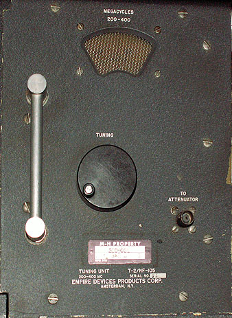
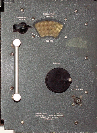
| The three "original" tuning plug-ins. When the NF-105 was first introduced - it's tuning range was limited to 20Mhz - 1000Mhz. | ||||||||
|
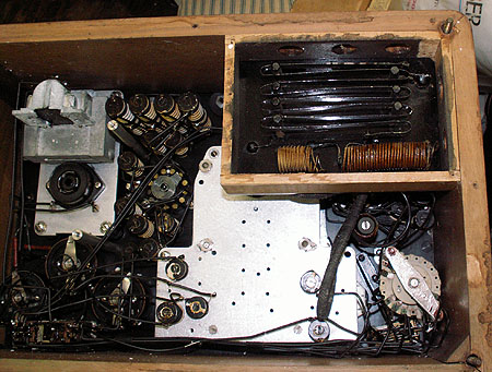
||||||||
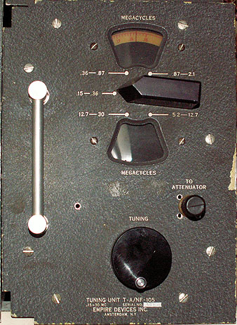
| Didn't take long for demand to extend the coverage of this system to first LF through HF - and eventually VLF. The VLF part of the spectrum introduced some problems that had to be dealt with. The NF-105's built-in calibrators could handle the LF - HF spectrum - so that first "increment" was fairly easy to accomodate - simply a plug-in that could tune from 150Khz to 30Mhz. However - calibration sources for VLF was another matter. The very complex TX plug-in was eventuallly introduced that not only tuned the desired VLF spectrum - but also had it's own "on board" calibration source - complete with it's own step- attenuator. The NF-105 signal attenuator is also not suitable for VLF - so the TX includes it's own antenna input with a "two step" attenuator (0db or 20db). Roughly half the facilities of the main frame PLUS the required tuning for the desired frequencies - all in a plug-in the same size as the "standard" tuning modules. Quite a feat of engineering - for the time. | ||||||||
|
||||||||
|
|
||||||||
|
Fluke
|
||||||||
 |
||||||||
|
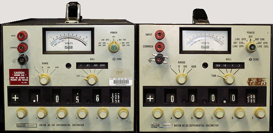
The great thing about differential meters is that at null (on certain ranges depending on the model) the input impedance of the meter is infinity. The ranges in this model - are the 1V and 10V ranges (up to 11 volts) . Above 11V - (100V and 1000V ranges) have a fixed DC input impedance of 10M ohms. 1000-0-1000V DC range; 0-1000V AC range with 10MOhm input as Transistor VM |
||||||||
|
|
||||||||
| Heathkit | ||||||||
 |
||||||||
|
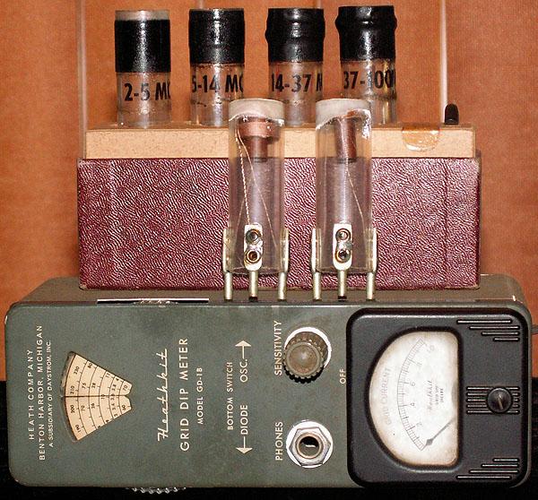
Can be used as grid dip meter (oscillator mode) or absorption Frequency Meter (Diode mode). Coil "A" 2Mc - 5Mc |
||||||||
|
|
||||||||
 |
||||||||
|
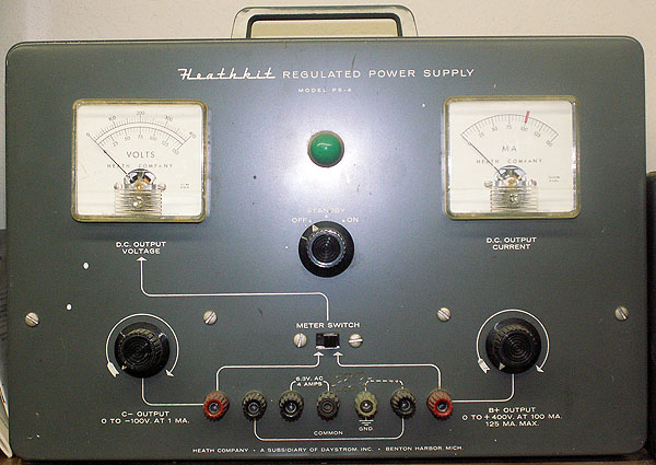
0-400VDC regulated - 100ma Cont. 125ma max 0-(-100)VDC 1ma. 6.3VAC 4A. Very useful in working on tube equipment - especially old radios. Supplies B+ and filament power to allow evaluation of the rest of the radio before the power supply portion is finished. |
||||||||
|
|
||||||||
| Hewlett Packard The long time standard by which virtually all other test equipment is measured - Hewlett Packard has always provided state of the art test and measurement equipment - along with a support structure second to none. While the price of new equipment is often too high for individuals to afford to own equipment of this caliber, fortunately - with HPs build quality and resulting longevity - a robust secondary market exists in affordable used equipment. While these older instruments may not be the latest and greatest with the most modern bells and whistles - they non-the-less provide excellent service to those who other wise would have to settle for mediocre and only marginally accurate equipment. |
||||||||
 |
||||||||
|
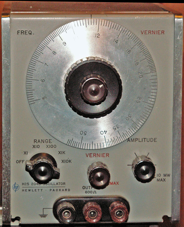
5 cps to 500 kc in 5 bands Dial accuracy of 3%. Maximum output level is 10 milliwatts into 600 Ohms, variable over at least 40 dB Distortion less than 1 %. |
||||||||
|
|
||||||||
| 204C - see 3550B below... | ||||||||
| 353A - see 3550B below... | ||||||||
| 403B - see 3550B below... | ||||||||
 |
||||||||
|
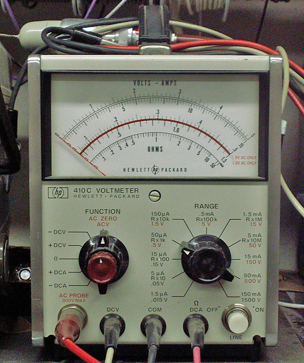
DCV +/- 15mv to 1500V +/- 2% full scale 11 ranges DC input resistance: 10MOhm 15mV -150mV ranges; 100MOhm 500mV range and above. ACV 50mv to 300V 7 ranges AC input impedance 1.5pf > 10MOhms drops @ VHF+ due to dielectric losses DC Ammeter +/- 1.5uA to 150ma full scale +/- 3%+/- 1.5nA to 15nA +/- 5% 10MOhm input resistance Looking over these specs shows why many people feel the 410 is the "Cadillac" of analog multimeters. |
||||||||
|
|
||||||||
 |
||||||||
|
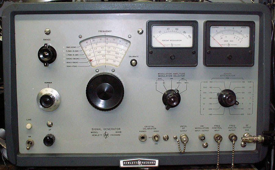
1% dial accuracy (against 100kHz and 1MHz calibration points). 400 and 1kc internal modulation, external modulation 0 - 95% .1uV to 3V into 50Ohms 1% accuracy. |
||||||||
|
|
||||||||
 |
||||||||
|
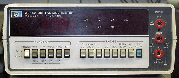
3.5 Digit Auto-ranging dual slope AC / DC volts: 200mV to 1200V AC / DC amps: 200uA to 2A (manual ranging only). Resistance: 20 Ohms to 20MOhms - special mode for diode check Reading hold: either special probe - or ground Amp connector. I still have the receipt from HP Richmond, VA when I bought this meter new in 1977 |
||||||||
 |
||||||||
|
204C Compact transistor audio oscillator. 353A Patch panel, 403B R.M.S. Meter |
||||||||
|
|
||||||||
 |
||||||||
|
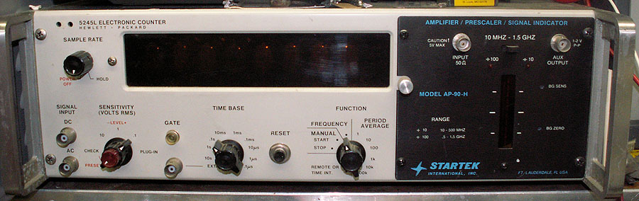
Gate: 1uSec - 10Sec - decade steps. Functions (without plug ins): Frequency, Period, Time Interval; Ratio. Timebase: 1Mhz crystal, controlled temp oven. Accuracy: less than 3 parts in 10minus 9 in 24 hours. Plug-in: Startek 500Mhz / 1.5Ghz prescaler (divide by 10 / 100). |
||||||||
|
|
||||||||
 |
||||||||
|
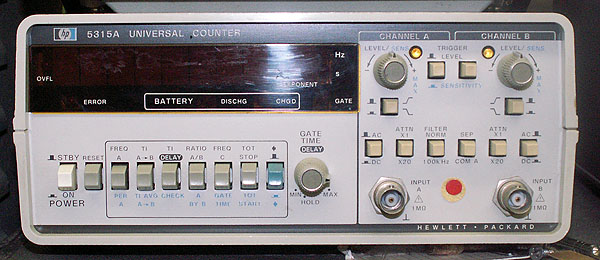
Functions: Frequency, Period, Time Interval, Time Interval Average, Time Interval Delay (Hold off), Ratio, Totalize. Timebase: 10Mhz. Accuracy: less than 3 parts in 10minus 7 in 1 month. |
||||||||
|
|
||||||||
 |
||||||||
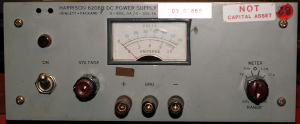
| 6206B Dual range power supply 0-30VDC 1ADC 0-60VDC .5ADC |
||||||||
|
|
||||||||
| Hickok | ||||||||
 |
||||||||
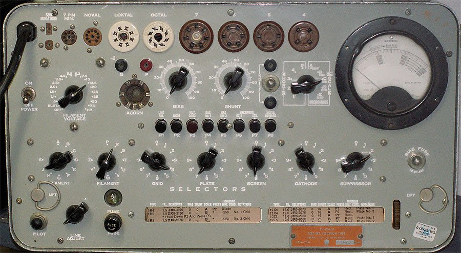
|
Filament voltage: .6 - 117V. Line Adj. +/- 10VAC Built-in roll chart. |
||||||||
|
|
||||||||
| Leeds and Northrup | ||||||||
 |
||||||||
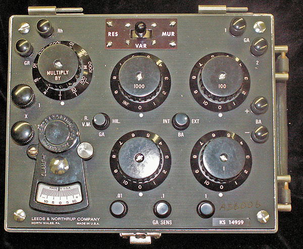
|
Special purpose bridge with built-in switching to provide quick setup for Murray and Varley loops. Before the days of Time Domain Reflectometers (think of TDRs as a special "RADAR" designed to "look down" cables) - the only practical method of finding shorts and opens in long distance cables were through the use of highly accurate resistance bridges setup connected to the wires in question in specific "loops" which facilitated determining the distance to a fault (short, open, etc.). Through the use of Murray and Varley loops - the distance from the end points of a cable to a fault could be narrowed to within feet in runs ranging into miles - saving much time in searching by hand. While we don't do much in the way of long-distance cable troubleshooting - this unit is also usable as a standard Wheatstone - simply by placing the mode switch to RESistance. Four decades of precision step resistors which can be set from 1ohm to 10110ohm. Range switch allows the bridge to balance between .001ohm to 1011000ohms (1/1000 to 100/1). Internal batteries can supply 4.5VDC for the bridge - while AC and DC can be supplied externally (up to 200V with limits). Our primary use is as a resistance standard for checking meters. |
||||||||
|
|
||||||||
| Mallory | ||||||||
 |
||||||||
|
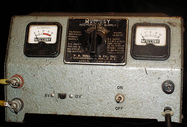
Rectopower model 12RS6D DC power supply 2-6V 10A / 4-14V 6 |
||||||||
|
|
||||||||
| Sencore | ||||||||
 |
||||||||
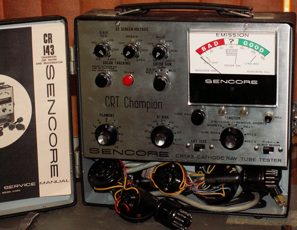
| CR-143 CRT "Champion" CRT Tester | ||||||||
|
|
||||||||
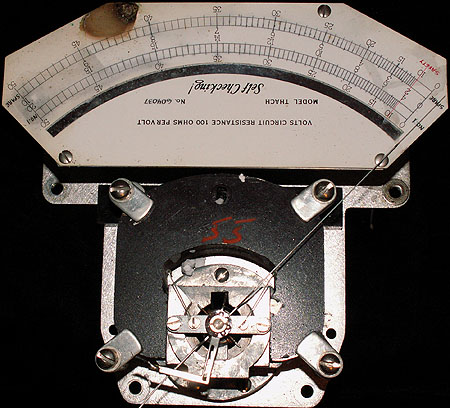
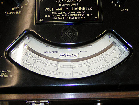
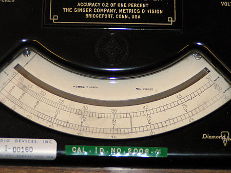
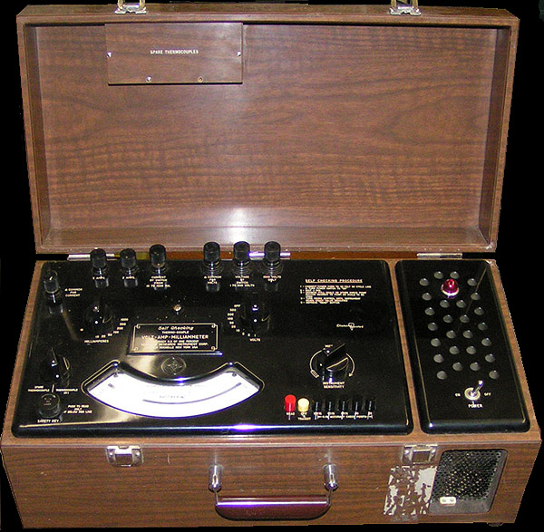
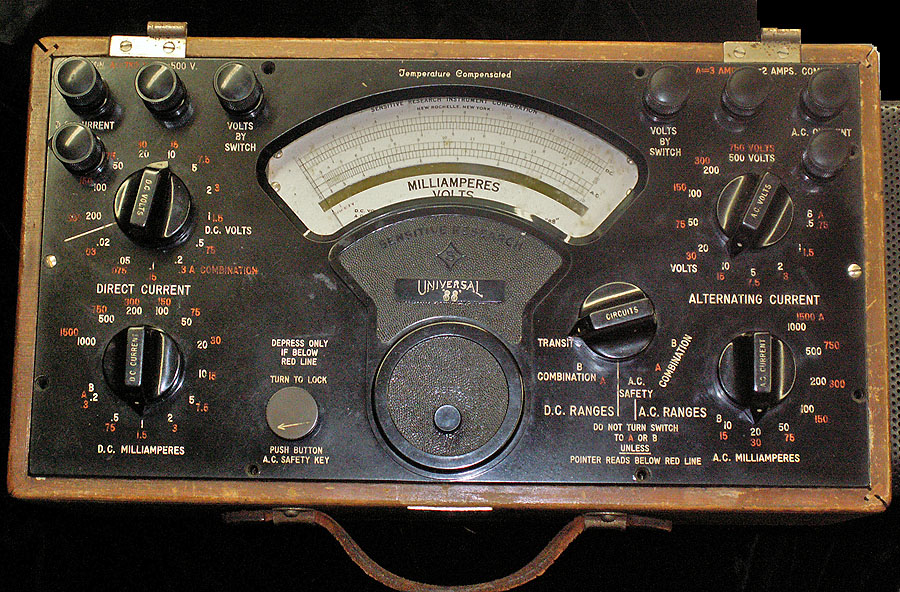
| Sensitive Research / Singer Metrics
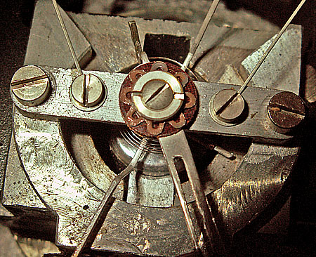
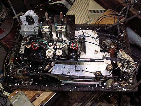
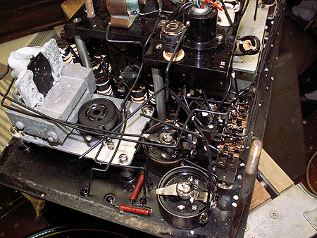
In 1927 - Sensitive Research Instrument Corporation (SR) was started with the goal of designing measuring instruments that would push the limits of technology - producing the most accurate instruments possible while staying within the limits imposed by the requirement that they were usable in the real world (as opposed to a strictly lab unit); and not so costly as to be considered impractical. Their work started with improving the Weston / D'Arsonval meter movement. While accuracy and sensitivity of the (then) current state of the art was good - the goals of SR was to better those factors by an order of magnitude. First was the magnet and it's pole-piece. At the time - rare element magnets were yet to be discovered - so the only way to improve on the existing magnets was size and tolerance. The magnet in the "standard SR movement" is not just large - but compared to most similar meters - massive. The tolerances are very close as well. The meter coil was improved - using a salt bobbin which allowed a complex internal design of the wound structure - which could not be accomplished with a traditional bobbin (after winding - the salt was dissolved leaving the complex shape behind). At first the coils were mounted between their jeweled bearing mounts using very precisely machined steel pivots. However- it was found that even less friction resulted if the machined steel pivot points were replaced with diamonds. |
||||||||
|
||||||||
|
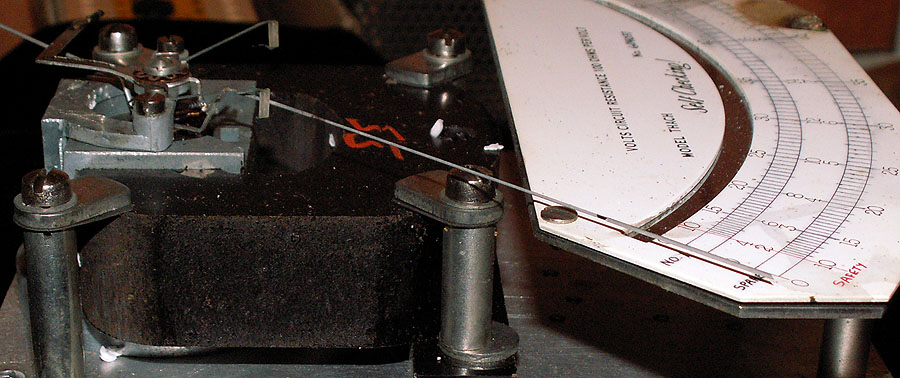
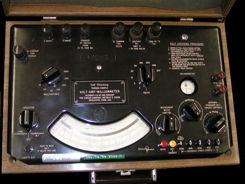
With these improvements - SR had the basis for some exceptionally accurate DC meters, but that was only half the goal - the other was to be equally accurate measuring AC. Root Mean Square is the mathematical relationship between a given value of work or work potential of AC and the same value or work or work potential of DC. Direct current - by it's nature - is performing work the entire time. AC - on the other hand - performs work in varying amounts depending on it's absolute (or peak) value at any given instant. Applying the formulae for Root Mean Square applied to many instantaneous samples over time - determines the equivalent work product of AC. This is exactly how digital instruments "measure" AC RMS today - taking many samples - then deriving an effective value and displaying that as the RMS result. Back when these instruments were designed - such high speed samplers and calculators didn't exist -- there wasn't any practical way to measure true RMS. So that was "the AC Problem": the technology to accurately measure RMS didn't exist. So just how do you measure what you can't? That sounds like nonsense -- but it really isn't. Let's look at a practical problem in geometry. Let's say you want to measure the height of a tree - but for reasons of safety, practicality, etc. you can't reach the top to physically string a tape measure along it's trunk to take it's measure. If you can't (directly) measure the tree - can you measure the effect of the height of the tree? At some point during the day - the tree is going to cast a shadow on the ground. If you know the angle of the sun - and measure the tree's shadow - some quick math will determine pretty accurately - the tree's true height (measuring the shadow of a 1 foot ruler can give you the angle). This is an example of determining some measurement by the effect of something - rather than directly measuring the thing directly. Was there a way to determined true RMS by measuring the effect of the current - rather than the current itself? Let's go back and review for a moment - There are three methods to detect or measure electrical current - magnetic, chemical and thermal. The D'Arsonval movement such as described above is an excellent implementation of using the magnetic property of an electric current to measure that current. It is not usable for AC, however - as it is polarity sensitive - and having a relatively slow response time - is useless for most AC measurements. Chemical indicators have never progressed beyond a curiosity in a laboratory, there are no practical implementations of such. That leaves thermal as the remaining technology to be applied to accurate AC measurements. The good news is that yes - thermal is quite accurate in converting a given DC or equivalent AC RMS into heat. A device in which 1 watt of DC that produces 1 calorie of heat - will also produce 1 calorie of heat when 1 watt AC RMS is applied. The problem is - that the linearity for either DC or AC over a given operating range of applied current, ambient temperature, etc is anything but good. Even with hand-selected components and extremely tight manufacturing tolerances - thermal converters (thermocouples in this case) are fraught with issue. However - Back when these instruments were being designed - thermocouples were the ONLY solution - warts and all. The engineers at SR set about to tame thermocouples as best possible- and fruits of their labor resulted in instruments that set the standards for many, many years. As with all electronics - temperature, humidity and physical shock, etc. can effect components from resistors to wire, from switch and binding post contacts - and of course the thermocouples themselves. All of these issues could contribute to inaccuracies creeping in with time - effecting the overall accuracy of the instrument. To detect and correct all of these issues - SR engineers developed built-in calibration devices which allow an instrument to both be on-the-spot calibrated -- and a provide an immediate confidence check of it's readings. One final step: Further - as noted thermocouples can exhibit some non-linear behavior depending on ambient temperature and aging of the device itself - so in their highest accuracy instruments - not only is calibration provided for at full scale - but at 20%, 40% 60% and 80% of full scale as well. This insures that at whatever level the thermocouple is being used at - the instrument can be calibrated very near that operating point - providing excellent accuracy of all readings. |
||||||||
 |
||||||||
The power source for the calibration generator in the instrument is 120V wall current (which has it's own regulation system). Either 120V has to be available at the measurement site - or the unit has to be transported between a power source and the measurement site - taking care not to disturb any setting - and sacrificing some accuracy under less than ideal conditions (temperature, humidity, etc. at both locations should be nearly the same - or accuracy suffers). Each THACH has two thermocouples - the operator can choose either. |
||||||||
|
|
||||||||
 |
||||||||
|
As can be seen - this unit originally belonged to Capitol Records.
Operator controls were added to the main panel to set the battery's circuit in balance to the Standard Cell (the control to calibrate the main instrument remains as before). A battery holder was added to the bottom of the instrument case - will an access door. The thermopile generator - now obsolete was removed making a smaller and lighter instrument. |
||||||||
 |
||||||||
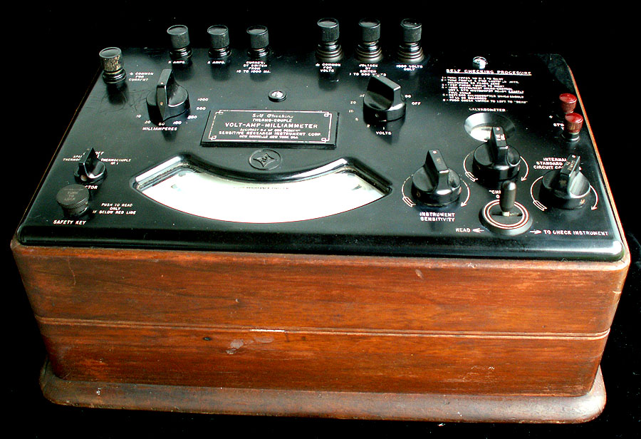
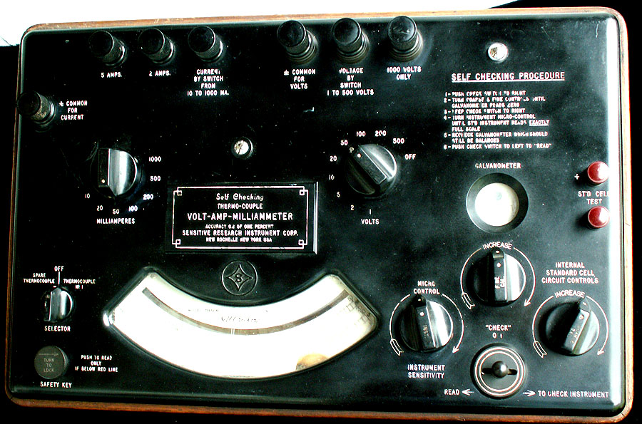
| Here is a THACH with Standard Cell Calibrator made while Sensitive Research was still located in New York. Unfortunately - this meter has had an extremely hard life - dropped hard enough to break internal mounts, bend things that shouldn't be bent - and then pilfered for parts - including the Standard Cell. Both thermocouples are present - although no idea yet whether they are any good or not. Being far too damaged to repair - this meter will serve out the rest of it's life as a shelf queen - and perhaps a source of parts for other units. | ||||||||
 |
||||||||
| This unit also has the old style "Read - Off - To Check Instrument" switch - which only provides one calibration point - Full Scale. | ||||||||
|
||||||||
|
||||||||
 |
||||||||
|
While .2% accuracy is nice - it's certainly not required for a lot of measurements - and the cost for that level of accuracy isn't inexpensive. Still - even at a lesser accuracy - true RMS is needed for a lot of analysis. The Poly-Ranger Universal "88" (for 88 total ranges) delivers very good performance at a much more modest price than it's exotic relatives. As noted in the main article - Sensitive Research Instruments also made many other "single range" and special purpose meters. We hope to add samples of those as time goes by (and budget allows). |
||||||||
|
|
||||||||
|
Simpson Electric Company
|
||||||||
|
||||||||
|
|
||||||||
|
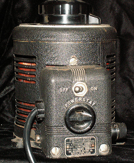
Superior Electric |
||||||||
 |
||||||||
| Powerstat Type 116 7.5A | ||||||||
|
|
||||||||
|
Tektronix |
||||||||
 |
||||||||
|
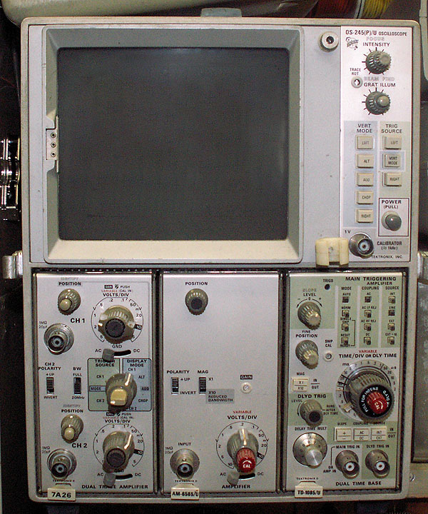
For nearly three decades - the Tektronix 545/A/B series oscilloscope was "the" workhorse for laboratories and precision electronics repair shops. From the 1960s through most of the 1980s the military had literally thousands of them. Accurate, versatile and reliable. There was one HUGE problem with the 545 - weight. Definitely a two-man lift - and most of the time in most shops the scope had it's own dedicated cart. They were a PAIN to carry any distance - and you can imagine trying to maneuver one around a submarine (yes - they were aboard every Boomer in the 70s) - or humping them deck to deck on a ship to get to a shop - or the cal lab. The "other" factor at the time was that Tektronix "owned" the 'scope market. Sure - Hewlett Packard, Dumont and others also made o'scopes - but by and large - when most people mentioned a 'scope - they meant a Tek. Hewlett Packard had long sought to get some serious penetration in that market - making military versions of several of their scopes. While competent for the most part (HP did have some scopes with serious trigger issues which sullied their reputation for a while) none of their offerings gained serious traction with the military. In the late 1960s - with transistors becoming more reliable, more acceptable bandwidth and greater power handling; HP saw an opportunity to build a 'scope that might give Tek a run for their money. By 1970 HP was producing their 180A 100Mhz bandwidth frame which weighed less than 25 pounds. It was an easy step - then to make a military version of that scope - equipped with mid-line performance plug-ins - the scope was light weight (about 40 pounds with cover and accessories), 50Mhz bandwidth dual trace, delayed sweep - all for only about $2500. The military started scooping up HP's OS-189/US281A. Here was the first "competent" o'scope that could move about a submarine easily - not to mention two guys weren't putting life and limb in jeopardy every time they had to unload a 'scope up through a hatch - or load it back down (OK usually the only guy in serious jeopardy was the guy underneath - but a 65 pound piece of equipment falling down a hatchway can be very serious!). Tektronix hadn't been idle either, though and had their entry a high-end lightweight (for the times) scope ready to go less than a year later. Sporting a three or four plug-in slot 100Mhz mainframe (which in later versions would reach a Ghz), and a fast growing family of competent plug-ins - the 7000 series was taking the civilian market by storm While HPs 180 series was a hit with the Army - and to a lesser extent - the Air Force; the Navy was still looking for some "bang for the buck". The Tek 7603 was definitely a great scope - but it was priced well beyond both the HP 180 (USM-281A) and the Navy's "budget wish-list" Taking the Navy's inquiries seriously- TEK started working with NAVELEX to see what compromises might be worked out. The result was a competitively priced 7603- - which with "options" N11S became OS-245(P)/USM-281C. Within a couple of years - a great many Navy and Air Force 545s were on the scrap heap- and a shiny new 281C in their place. As they say - the rest is history... Well, not quite - turns out the "281" contest wasn't over, not quite yet - as a third entry showed up by late 1973 /early 1974: Dumont "ruggedized" their model 150 to meet the "basic" specs of the 281: 50Mhz dual trace frame with a competent vertical and horizontal plug-in. This didn't have the "bells and whistles" of either the HP nor Tek versions; this was a back-to-basics no non-sense scope that just worked - and worked well. Very rugged, reliable (the only consistent problem they had was if the heatsink got clogged or blocked - the 2N3055 series-pass transistors in the power supply would give out. As a basic - and very cost effective work-horse - the Dumont should have won the war. But the other two just had too much traction. The only reason the Tek didn't totally blow out the HP - was the double-edged sword of the buttons on the horizontal plug-in. They quickly gained a reputation of being too fragile - too easy to break off if smacked. Never mind the scope was supposed to have it's front cover on when transported (and usually did) - "the word" was out in the Navy - and many commands shied away for that reason. The buttons has already been an issue early in the design of the 281C - as they were also used on the mainframe to select vertical mode and trigger source. Since the main-frame panel was already re-designed due to the removal of the readout system - Tek had substituted larger - less fragile buttons on the frame. However - there were too many on the timebase plug-in (which is a "rebranded" 7B53AN) - and since the plug-in simple to replace if damaged - the small buttons remained on the TD-1085/U. I *never* saw a broken switch on a 281C during the two years I ran test equipment repair and the test equipment loaner pool for Subron 15 aboard Proteus (Apra Harbor, Guam 1974-1975) - but you know how rumors are once started... The Tek's versatility was - and still is - remarkable. An incredible array of plug-ins were available- and being Tek - the 7603 and it's siblings took off in the commercial market. It's interesting that while HP made nearly as many plug-ins for the 180 frame - few people realize that fact - and just assume the Tek is far more "versatile". Regardless of the facts - the dominant factor for collectors (and technicians that still use the 'scopes) is that the available "stuff" for the 7000 series is nothing short of awesome - while the HP-180 / HP1800 series has almost faded from memory. Our Tek is a standard USM-281C - with the stock set of plug-ins. We have picked up a couple of 7A26 dual-trace plug-ins - which gives us 1 to 4 traces - and a host of modes. Might pickup a 7L13 Spectrum Analyzer some day - you never know.... |
||||||||
Recent breakdown and repair of our USM-281C |
||||||||
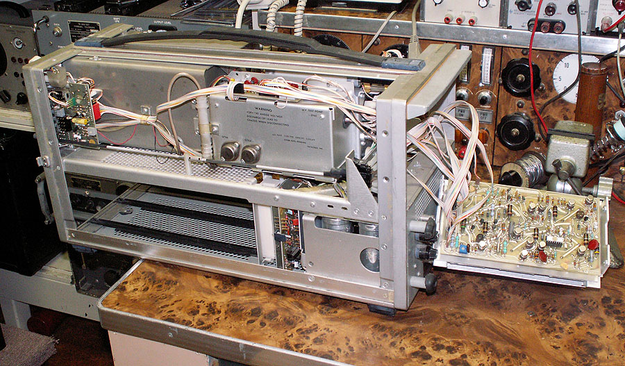 |
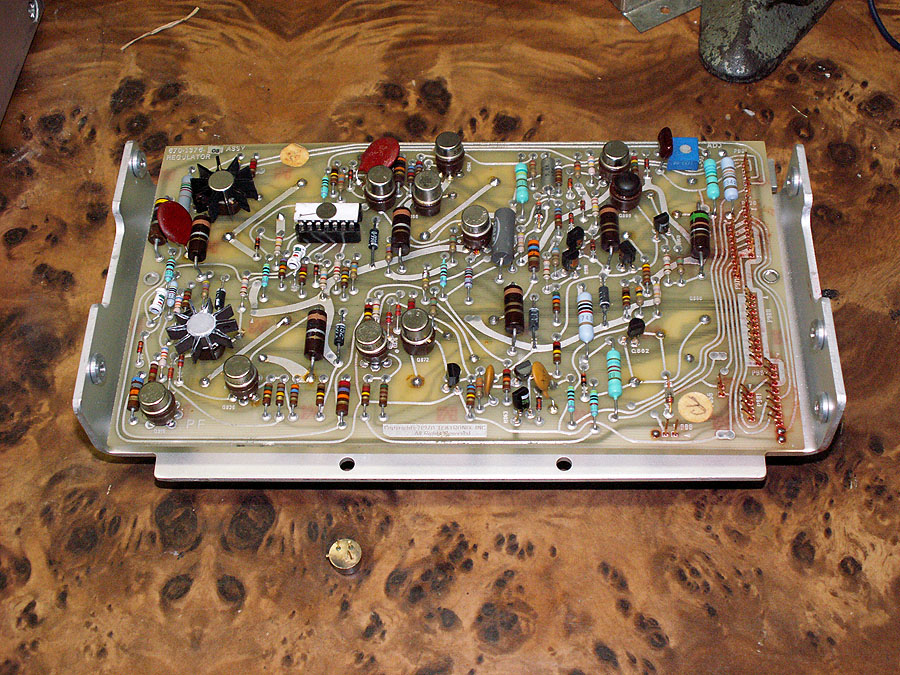
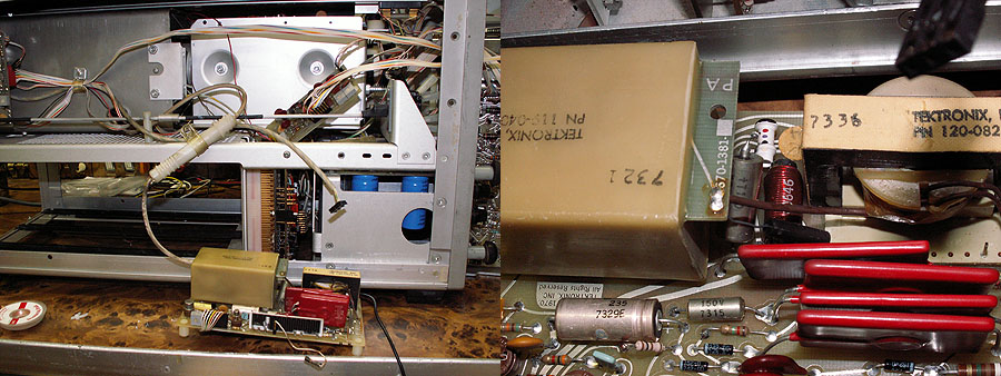
Most of the major assemblies in the scope are modules which can be swung out and worked on. Here - the low voltage regulator board is being worked on. |
|||||||
|
I was working on a piece of equipment on the bench using the scope - when the scope died. This is the first failure since we've had it - some 20+ years - and being made in 1973 - it's 37 years old - and obviously - had some hard use in the Navy before I got it. Turned out the +15V series pass driver had "given up" - the base-emitter junction going open. An NTE128 is a suitable replacement but being out of stock locally - I had to order a couple. Since such a failure is a bit uncommon - I decided to check the power supplies closer. |
||||||||
 |
||||||||
| The repaired board with failed TO-39 transistor on the bench. The red on all the pins is DeOxit. | ||||||||
|
To get the +15V back up temporarily - I used an NTE157 - which is a very similar transistor to an NTE128 - just in a TO126 tab vs. TO39 can. Looking at the regulated supplies - they all looked good - but I also noticed the +15 series pass transistor seemed a good bit warmer than any of the other 5 on the back heatsink. It is the highest current / dissipation device of the 6 - but not by all that much. Checking the ripple - the raw rectified power for that supply had more ripple than the others. Using my capacitance ESR tester - sure enough - all the other caps measured better than min spec. for both capacity and ESR - but the two filter caps in this circuit (two 9600mfd in parallel) measured considerably lower capacitance than rated - and borderline high ESR. Apparently - the higher ripple content was causing the dissipation of the series pass to be just a tad more, and since it's driven by the driver that failed - it was also being taxed more than usual. So - in goes an order to Mouser. Since orders usually take two days to get here (I'm cheap and only pay ground UPS shipping) - so I had a little spare time... Of course - I can't leave well enough alone - so I have to fiddle about a bit. One task is to pull every transistor, IC and cable connector from their sockets - and treat all the pins and sockets with DeOxit. Didn't take all that long. |
||||||||
 |
||||||||
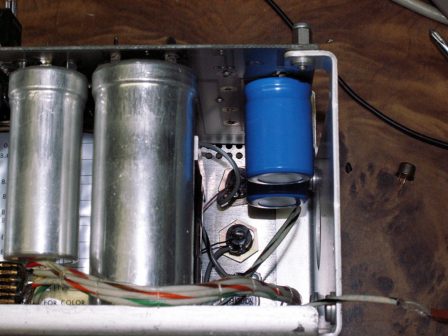
| The replacement capacitors are installed - the remaining caps (which are pretty much the size of the replaced caps) dwarf the new ones. | ||||||||
 |
||||||||
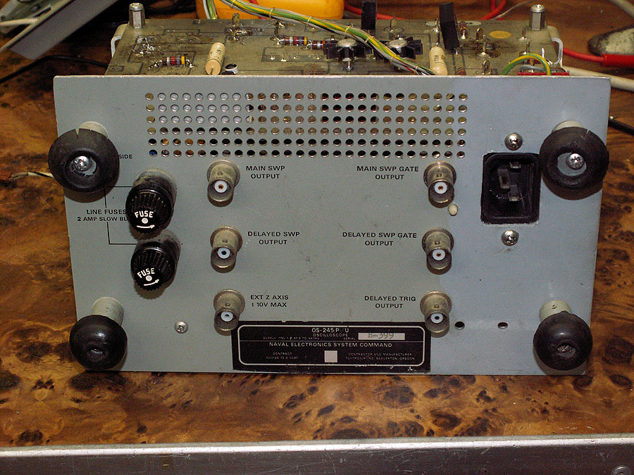
| One thing about the USM-281C (and it's 7000 series cousins for that matter) that I've never liked - is the permanently attached power cord - it's a pain in the butt, especially when taking it mobile. So of course this is an excellent opportunity to replace the fixed cord with a standard IEC power socket. Since the scope's line filter also serves as the terminals for the power cord, replacing it with a combination IED socket with built-in line filter worked out very well. Of course, the area where the socket was fitted needed a dab of paint to look respectable - as if anyone would notice. This again shows another module out of the frame. | ||||||||
 |
||||||||
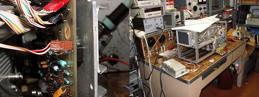
| Left: several connectors to/from the regulator board. The two wire connector near the center was the "problem" connector. Making sure that this problem doesn't bite someone else in the future - I've swapped the brown and red wires so that when the arrow on the connector and the arrow on the board line up - it's right. In the right picture - the HV module has been pulled and is laying on the bench for troubleshooting. | ||||||||
|
Once the new caps and transistor were installed - I brought the scope up gently - only to find something was VERY unhappy - the +15V supply I had just "fixed" was only putting out about 4V and the pass transistor was getting VERY HOT!!!... To make a long story short - here's what happened: As noted - Tek and the Navy had worked out some changes in the 7603 to both ruggedize it - plus save some costs. One of the "shortcuts" was to eliminate the on screen "Readout" system - saving several boards and many parts. One result of that compromise was several cable needed to be re-routed - and in a couple of cases entire boards made "custom" for the 281C. This meant that not everything "matched" as "cleanly" as it did in the "stock" 7603. It was one of these "changes" that "bit" me... The cables in the 281C are point-to-point ribbon cables that have plastic shells that hold and identify the wires. Each connector "end" has two specific functions (besides the obvious bit of holding the wires): one is to help identify which cable is which - and which wire is which - and which way they "mate" with the pins on the board(s). The first identifier is by the color of the connector itself - being plastic - they can be made in any color - so Tek uses a color that is the least significant digit of the connector number. Connector shell for P890, for instance - would be black - as in 0 = black - so the connector for P862 would be Red (2 = red); P904 = Yellow, and so on... Wire colors follow the resistor color code: the first wire is always brown (brown = 1); then red (red = 2), orange (orange =3); and so on. On the connector shell - the first wire position always has an arrow pointing to it - and there is an arrow pointing to the number one pin on the circuit board. So to put the connectors back on the boards- you just line up the arrows, making sure the number of wires is right - and the least significant digit and the connector's shell color match. Right. Until I found out the hard way that not only is it possible that one of the connectors isn't "wired" right - but that the big Navy manual for the beast (NAVELEX 310-40-6090) is also "wrong" --- such that one connector is "supposed" to be plugged in "backwards". Of course that means that I hooked up the B+ feed and return power cable to the HV power supply module "wrong" - which then fed the wrong polarity voltage to the high-voltage module - which has now itself failed with something shorted - and is now taking the +15V supply with it. Fortunately-- it appears that the only damage was to a small electrolytic on the HV circuit board. |
||||||||
 |
|
|||||||
|
Replacing that brought the scope back up for a short while - but something was still not right - blanking wasn't working right; other things were also - "weird". Checking about soon found that the 130V power supply was only about 90V. Since TEK wanted to use the same transistor for all of the series pass supplies - (a heavy duty version of the ubiquitous 2N3055); they had to get inventive in order to use that 100V rated transistor in a 130V supply. Their solution was to work from the +50V supply - regulate that to around 40V - then use that as the "foundation" for a 90V fixed supply in series with it. The 2N3055 could now easily regulate the 130V supply - while actually only "seeing" less than 50V. Turns out - the driver for the 40V supply had opened - however - in this circuit the driver is a smaller signal transistor - and a PNP at that - basically a 2N3906. Installing a new transistor - and all the supplies suddenly were a mess. Being careless - I had installed one of the cables wrong. It was on the right set of pins, alright - but unfortunately - off-set one pin. The only thing that did was run +15V momentarily onto the +5V bus. Fortunately - the supply shut down before too much damage was done - in fact - only one Tantalum capacitor - in the Timebase plug in- failed. Lesson learned - don't get in a hurry - and don't work too tired... Ain't worth it. Replacing that 33ufd 10V tantalum returned the scope to good working order. (Whew! - could have been a LOT worse- remarkable a lot more damage wasn't done. ). |
||||||||
 |
||||||||
|
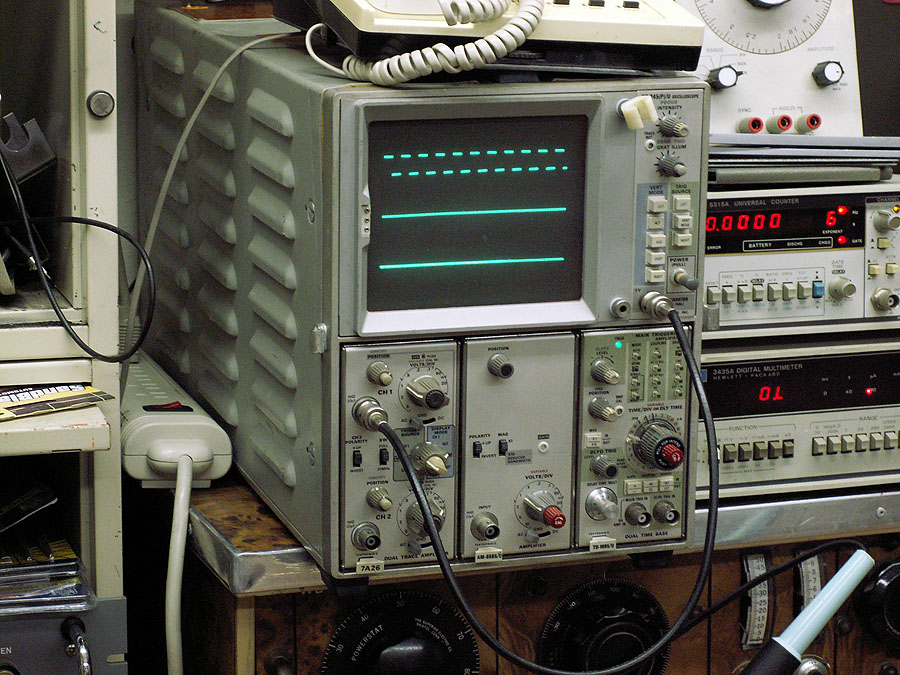
The now completely repaired scope back in it's place above the bench - rather than on it - ready to go back to work. |
||||||||
 |
||||||||
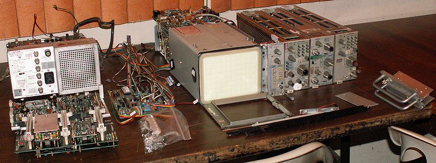
So - is this the fate of a piece of equipment that dares to mis-behave after being fixed? Not hardly. This IS, however - less than 24 hours after this unit arrived here. In fact - those with a sharp eye will undoubtedly already have realized this is a 7603 (vs 281C) - and in fact a 7603R (rack - the rack ears are a good hint). A few days ago - a 7603 showed up in one of the "saved searches" I have on ebay - it looked promising (it appeared complete; the seller has a fairly good feedback record - and it's not far from here (keeping shipping reasonable)- So I "tagged it" by placing a minimum bid - just so I could easily get back to check it out at a later time. Of course - I then promptly forgot all about it. Until about a week later, that is - when I received the "Congratulations - You Bought It" email from eBay. 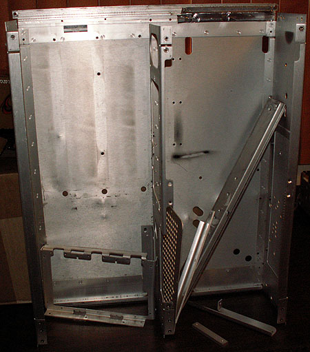 Well - considering my minimum bid was $14.99 and even with shipping the total was still under $50.00 - Yeah - I was now the proud owner of a parts unit - a source of spares for my USM-281C. Looking it over - it had obviously had a rough life - some major dings in the cabinet here and there, the frame that holds the plug-in connectors and circuit boards was "bowed"; the vertical mode selection switch jammed and wouldn't work- but still - most everything looked pretty good. I also noticed one reason some things looked just a bit "different" - this unit was made by Tektronix Holland. Interesting. What the heck. Plugged it in and fired it up. Figured worst it would do is blow a fuse (the 7000 series are well protected by both several fuses - and fold-back power supplies). No graticule illumination - Hmmm... But then you can imagine my shock - and delight - as two traces and the "readout" appeared on screen! Amazingly - it works! Further poking about leads me to believe that this is a very late production unit - if I'm reading the date codes right - roughly 1986 or 1987 - some 13 years newer than our 281! Well - considering my minimum bid was $14.99 and even with shipping the total was still under $50.00 - Yeah - I was now the proud owner of a parts unit - a source of spares for my USM-281C. Looking it over - it had obviously had a rough life - some major dings in the cabinet here and there, the frame that holds the plug-in connectors and circuit boards was "bowed"; the vertical mode selection switch jammed and wouldn't work- but still - most everything looked pretty good. I also noticed one reason some things looked just a bit "different" - this unit was made by Tektronix Holland. Interesting. What the heck. Plugged it in and fired it up. Figured worst it would do is blow a fuse (the 7000 series are well protected by both several fuses - and fold-back power supplies). No graticule illumination - Hmmm... But then you can imagine my shock - and delight - as two traces and the "readout" appeared on screen! Amazingly - it works! Further poking about leads me to believe that this is a very late production unit - if I'm reading the date codes right - roughly 1986 or 1987 - some 13 years newer than our 281!
This then - presented something of a dilemma - whether to try to refurb this unit - as it's much newer and has the "readout" feature that the 281 doesn't have - or - use it as intended - a parts source for the 281 - we sure don't need two working scopes!. The decision - for the time being - was pretty easy. The 281 is in really good operational shape - and unless you're using one of the specialty plug-ins (like the spectrum analyzer - or curve tracer) - the readout is not that important. So this unit was "scrapped out". It now takes up roughly half the room to store the parts as the whole unit took. It's not that they aren't all that compact - but without case and frame, etc. - a lot of room is saved. The 7A18 dual trace plug-in is also easy to "store" as it's in the middle slot in the 281 - giving it 4 trace capability. It's also nice having a spare horizontal time base plug-in - that would have been "handy" when we were having trouble with the TD-1085 (7A53AN) plug-in. Sherry has already claimed the frame parts - seems she almost has a load of aluminum drink cans ready to go - and she figures they'll like this aluminum as well... As far as adding in the "readout" system... That's way more complicated than one might think. It's not just a missing board or two and a few wires - almost every subsystem in the scope has some input/output to/from the readout system. The Interface board - with both the vertical amp and synch selector boards, The entire main-frame control assy.; the horizontal amp, and so on - all those boards have to be replaced - as the readout related parts of those boards in the 281 simply do not have the needed support parts. Afterall - the 281's "Tek" designation is 760311N (ruggedized w/no readout). So unless I get some plug-in (spectrum analyzer, etc.) that would truly benefit from the readout capability - I'll just use the 7603R as a parts bank against some future failure. I can't believe some of you thought I'd junk out the 281 if it misbehaved... |
||||||||
 |
||||||||
| Sherry checking out the "landing site" for the "air mailed" URR-13 radio... This was a real piece of junk radio - and the flakely VFO oscillator section crapped out all too often... by the time you'd get "in to" it... it'd be working, of course. Back together - in the rack - and dead. Again -- One time too many |
||||||||
|
|
||||||||
|
Weston |
||||||||
 |
||||||||
|
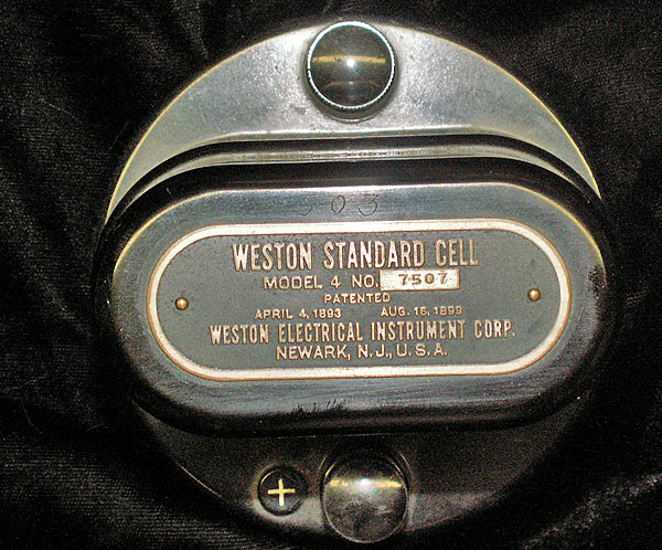
There are two types of Standard Cells - the saturated cell - and the unsaturated cell. Saturated cells are the most accurate over time - but their output is effected by temperature - which must be taken into consideration when used. Unsaturated cells are much less sensitive to temperature- so are preferred for most laboratory use. However - they do loose approximately 80uv per year - so they need to be compared to a saturated cell every-so-often to determine their absolute output. A new cell has potential output of 1.018638 volts. If one knows the age of a cell - it's output can be calculated fairly close by subtracting 80uv per year. This particular cell is believed to be nearly 25 years old- and measures (averaged between two calibrated digital meters) 1.01684 volts - which would work out to about 72uv per year (calculating 25 years). Having such a reliable voltage source for checking our own meters is really nice. |
||||||||
|
|
||||||||
|
|
||||||||
Visitors:
 |
||||||||
|
|
||||||||
| © 2010 Randy and Sherry Guttery | ||||||||