|
|
||||
 |
||||
|
|
||||
| The Bench | ||||
|---|---|---|---|---|
| This article is being re-worked - and is a work in progress. Thanks for you patience and suggestions along the way! | ||||
| I've had many people ask about "The Bench" over the years - and I have always shared the schematics. With the popularity of the Internet - and the exchanges of ideas, etc. - when I got flooded with requests after "The Bench" was talked about on some news groups, it seemed a good idea to update my own hand drawn schematics, and notes - and share them with everyone through a web page.
A few things to keep in mind - this was a project that was done many years ago- using parts, etc. that were on hand. That means that there are compromises in circuits and parts - both from the standpoint of what was "on hand" and the technology of the time. That also means this isn't the best way or "right" way of doing things - just how it was done "back then". When I saw a long time ago - the panel, it's circuits, etc. were designed and put together in the 1976/7 time frame. Still - there are some good ideas - and - considering "The Bench" is still in use nearly every day (and has had only some minor issues over the years) - some things were very good ideas... If fact - the only outright failures (besides needing to clean switch contacts and such) has been indicator lamps in the switches - and the main 28 volt power supply - which was a commercial unit - and it was the victim of lightning. |
||||
|
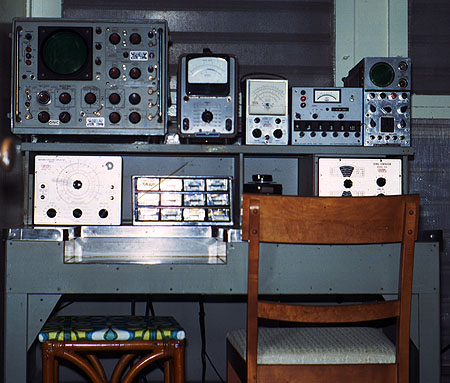
The basics - why build this thing. Beyond the obvious need for an organized work area - in working with electronics equipment - there are a few things that are needed regardless of the technology being worked on. One is a controlled soldering iron - or soldering station. Whether working on tiny fragile semiconductor circuits - or large heavy duty tube / industrial control items - soldering remains a constant - just the amount of heat changes - and having a variable AC source to control the soldering tool is a great far more a requirement than luxury. One might make the case that a controlled temperature solder station would suffice - however - in my experience - while fine for a limited range of needs - the ability to radically crank up (or down) the amount heat available from such tools is limited. With a controlled outlet - one can use anything from a 25W pencil (or 35W or 45W elements) to an American Beauty monster iron - and still control the heat precisely. Usually a 35W element in a handle with a chisel tip is all I need from fairly small IC work to rather heavy wires in a UPS or other high-current device - accommodating each need by merely dialing up (or down) the variable transformer. Of course - that outlet can also be used for any other AC supply need - as long as it's within it's 0 - 130V 3A range - and measuring current draw isn't important. A second "good to have" item is a "test" AC power source. Handy to have built-in - with voltage and current metered; and fused for safety. Even better is a sensitive, fast current limit system to protect the load in case of a problem. In this case an 8Amp variable transformer supplies power to an outlet on the bench work area - which is metered for voltage and current; has an 8Amp fuse - plus a 1Amp or 4Amp electronic circuit breaker system that ignores short transients - but reacts very fast to overloads that last more than a few milliseconds. The sense circuit is in the variable transformers output - so it doesn't "see" the inductive kick from the variable when it's switched on. A third "good to have" item is a lab quality DC supply. In this case - a 0-30 Volt power supply built from the circuit designed by National Semiconductor (Their Liner Brief 28 (LB-28)). Taking it's input from the bench's 35V fixed supply - it is capable of sourcing up to 10A (or sinking up to 1A) at 0 to 30V output. The series pass devices are LM395s which are mounted directly to the rear panel of the beach - providing a huge heat sink for the up to 300W of dissipation the supply is capable of generating. At the time - the thought was to also add another "section" of built-in capabilities to the bench - air supply (adjustable 0-125psi); high suction, low volume vacuum (adjustable 0-20in.); low suction high volume vacuum (vacuum cleaner). Had I known then what I know now - I'd have left that section out - as it's so seldom used. The vacuum cleaner is a good idea - but not where it is - not out the front panel. The large stiff hose is a royal pain to use in such tight space, better to have the hose "loose" and out of the way when not in use. High pressure air is OK - but tends to blow dust everywhere. Better to use a vacuum as described above. High suction low volume vacuum. Well - again the idea is OK - but you either need it - or you don't. Having an adjustable vacuum is - well it's just not needed. Admittedly - figuring out how to change a pressure regulator into a vacuum regulator was a challenge - and one I managed to meet. Too bad it's not practical for anything. A lot of machining, etc. for nothing. Bad idea - wouldn't do it again. So what are the good ideas here? As noted - the two controlled AC outlets are used a lot. So much that the outlet itself needed to be replaced about a year ago (2009). Slap wore out (and it was an Eagle commercial grade!). The DC power supply has worked out very well - though today - I'd probably just get a commercial supply with remote capability and use that instead of building one. But by far - the electronic circuit breaker has proven it's worth many, many times over. I have no idea of how many times it's done it's job and protected something that more traditional fuses or circuit breakers would have just let fry. That alone (well plus the actual working area) was well worth the effort in "The Bench". |
||||
|
|
||||
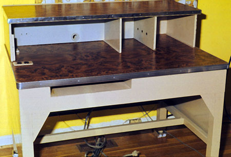
| The Desk - aka: the steel beast... | ||||
|
||||
|
||||
|
|
||||
| Electrical / Electronics - what, how and why... | ||||
| There are several major "divisions" of electrical / electronics in the bench: Primary AC distribution and supply; Controlled AC; Auxiliary Controlled AC, Primary DC distribution and supply; and Control and Monitoring circuits. | ||||
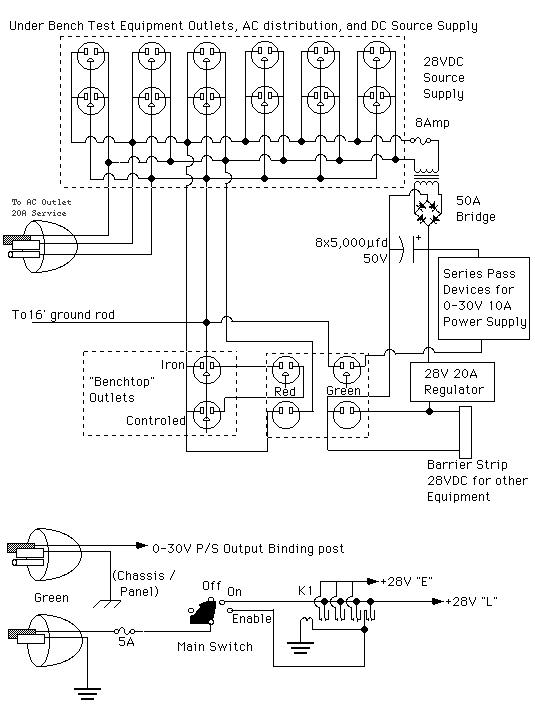 Primary AC & DC consists of a heavy gauge power cord that plugs into an AC outlet (and so obviously always energized), and passes through a 20 amp fuse; then on to several AC outlets below the bench that are "hot" all of the time. Most of the test equipment and Primary DC (28V) supply are plugged into these outlets. AC power is also suppled to the control panel as well as being returned to the bench as Controlled AC through a special set of connectors. Primary AC & DC consists of a heavy gauge power cord that plugs into an AC outlet (and so obviously always energized), and passes through a 20 amp fuse; then on to several AC outlets below the bench that are "hot" all of the time. Most of the test equipment and Primary DC (28V) supply are plugged into these outlets. AC power is also suppled to the control panel as well as being returned to the bench as Controlled AC through a special set of connectors.
Controlled AC is taken from the control circuits of the control panel - and fed (via special connectors) to the two AC outlets on the bench's work area. The "Iron" outlet is controlled by the 3Amp variable transformer and it's control circuits; the "Controlled" outlet is controlled by the 8Amp variable transformer and it's control circuits. Primary DC. The original main DC supply was damaged by lightning some years ago - and replaced by a commercial fixed supply capable of 32V, at 25A continuous and 40A surge. Being a commercial supply - it's plugged into one of the always on AC outlets (the schematic hasn't been updated) so it too is always energized - and is distributed to the control panel and to external terminals -- where it is available to power external devices - such as Sherry's R-391, etc. The control lines for the 0-30V supply are not shown here. Main Switch. The key switch is a typical automotive type ignition / start switch. The "Ignition" and "Start" positions are used the Auxiliary contact is not (turning the key that way does nothing). Circuit is show in the off position. Nothing past here works. Rotating the switch to on ("ignition") energized the lamp power circuit (abbreviated as "L"). This supplies power so that the lamps can indicate what WILL happen once power is actually supplied. Keep in mind - the only thing powered right now are the lamps, nothing else. Once the key is rotated to Enable ("Start") - K1 is energized and one of it's contacts latches it to the "L" line. The other three contacts supply power to the control circuits - via the Enabled line ("E"). The only way to unlatch K1 is to turn the key switch off. The purpose of this will be explained later. |
||||
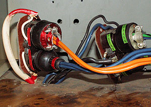 Here are the Red and Green "special connectors". The ground lugs are not used electrically - so the upper plug of each "set" has it's lug in place - while the lower receptacle of each set has a "blocking pin" inserted so that the upper plug will not go into the lower socket. The "sets" are done so that the absolute worst that could happen should the red and green plugs somehow get swapped - would be a bow fuse. Here are the Red and Green "special connectors". The ground lugs are not used electrically - so the upper plug of each "set" has it's lug in place - while the lower receptacle of each set has a "blocking pin" inserted so that the upper plug will not go into the lower socket. The "sets" are done so that the absolute worst that could happen should the red and green plugs somehow get swapped - would be a bow fuse. |
||||
|
|
||||
 |
||||
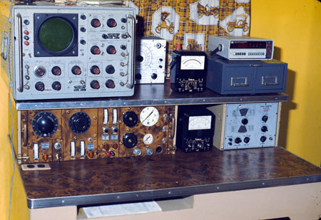
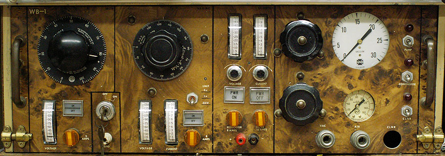
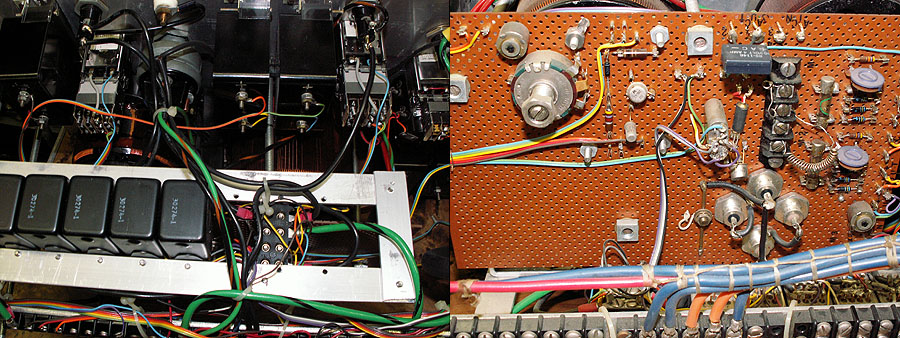
| Close up of the control panel. | ||||
|
|
||||
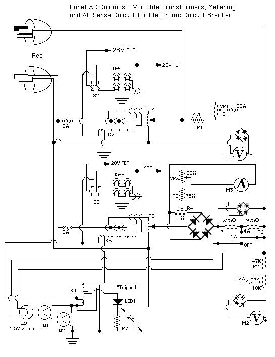 Control and Monitoring circuits. Once the Enable line ("E") is energized, the various switches can now control their respective devices. In the top section of the schematic at the right we see the two AC connectors (these are better explained further down). The lower Red connector brings in AC power - neutral and Line. Through a 3A fuse, Line is applied to three of the contact sets in relay K2 - now shown de-energized. Lamp power (via "L" line) connects via one set of K2 contacts to light either the right-hand "On" or "Off" lamps in the control switch S2. Since the relay is not energized (and S2 is not pressed) both the left and right hand "OFF" lamps are lit. When S2 is pressed - the left hand "OFF" lamp extinguishes and the left hand "ON" lamp lights. Virtually instantaneously - Relay K2 energizes - switching it's contacts. The right-hand set of contacts de-energize the right-hand "OFF" lamp and light the right-hand "ON" lamp in switch S2 - the remaining three contacts switch and supply power to the top of variable transformer T2 (it's bottom tap is connected to AC neutral). Whatever voltage is being "tapped off" of T2 by it's rotating contact is connected to the "Iron" outlet on the bench top via connector Red 1 (upper plug). The meters are 2.75ma. full scale with an internal resistance of 12ohm. So the 47K provides proper scaling - and 10K variable provide proper calibration "tweaking". The diode bridge (in this case 4 1N914s) rectify the AC for the meter. Since variable transformers put out a "mostly" sinusoidal waveform - the meter can be set to read a good approximation of RMS (though it's really reacting to average). Note the 20ma fuse in the meter's circuit - that is "just in case" - but hasn't "blown" in 30+ years of service. Control and Monitoring circuits. Once the Enable line ("E") is energized, the various switches can now control their respective devices. In the top section of the schematic at the right we see the two AC connectors (these are better explained further down). The lower Red connector brings in AC power - neutral and Line. Through a 3A fuse, Line is applied to three of the contact sets in relay K2 - now shown de-energized. Lamp power (via "L" line) connects via one set of K2 contacts to light either the right-hand "On" or "Off" lamps in the control switch S2. Since the relay is not energized (and S2 is not pressed) both the left and right hand "OFF" lamps are lit. When S2 is pressed - the left hand "OFF" lamp extinguishes and the left hand "ON" lamp lights. Virtually instantaneously - Relay K2 energizes - switching it's contacts. The right-hand set of contacts de-energize the right-hand "OFF" lamp and light the right-hand "ON" lamp in switch S2 - the remaining three contacts switch and supply power to the top of variable transformer T2 (it's bottom tap is connected to AC neutral). Whatever voltage is being "tapped off" of T2 by it's rotating contact is connected to the "Iron" outlet on the bench top via connector Red 1 (upper plug). The meters are 2.75ma. full scale with an internal resistance of 12ohm. So the 47K provides proper scaling - and 10K variable provide proper calibration "tweaking". The diode bridge (in this case 4 1N914s) rectify the AC for the meter. Since variable transformers put out a "mostly" sinusoidal waveform - the meter can be set to read a good approximation of RMS (though it's really reacting to average). Note the 20ma fuse in the meter's circuit - that is "just in case" - but hasn't "blown" in 30+ years of service.
In the lower part of the schematic at right - is the variable transformer T3 and it's control circuits - which as far as input / switching, etc. are identical to T2's circuit above - except for K4 in K3's return line. K4 is part of the "electronic circuit breaker" used with this variable transformer. The output has two additions to the circuit of T2: An amp meter and it's associated shunt and scaling resistors; and the RMS current sense circuit for the "electronic circuit breaker". The first difference in output - is the addition of an ammeter circuit - so an current draw of any device plugged into this outlet is easy to monitor. T3s output is routed through a 15A bridge - whose "DC output terminals" has a .1 ohm resistor across it. Why not just run the current through a resistor then use small rectifiers like the Voltmeter above? Has to do with the voltage drop across the diodes. Small signal rectifiers have about a half volt (.55V actually) across them at normal forward current levels. That means to indicate any current - our shunt would have to deliver at least 1.2 volts. Let's say that is what it delivers at 1Amp (i.e.1 ohm shunt) Ok - then at 10Amps - were dropping 10V - way to much - and 1) the shunt is hot (10 watts) and 2) we're not chewing up a lot of voltage that never gets to the load... Using high power diodes (or a bridge) each element drops roughly 1 volt - so a bridge drops 2V - but that's regardless of current. And if our shunt only drops another say .3V at 10A - That (.3V) is the only variation in output voltage that is current (ammeter) caused. If we take our voltmeter off behind the ammeter - then it indicates what the load is seeing. By placing the shunt across the output of the bridge - all of the AC current flows through the shunt - (now pulsing DC) and the diode drops aren't between the shunt and the meter. The meter is 2.75ma. full scale - 12 ohm - so calculating: .00275*12=. The shunt we are using is a piece of a 10Amp shunt out of an old Simpson 260 multimeter. The part we're using is about .1ohm - and we have the "tap" at about .03 ohms or so. So .03 ohm * 10A = .3V. The meter needs .033V - so a little calculation .3V-.033V = .267V .267V/.00275A= approx. 97 ohm. Since it's very hard to make "accurate" adjustments with the "tap" we just get it close (on the high side) and use the variable (VR3) to "tweak" it in. Next item - the "electronic circuit breaker". Measuring average AC current is easy - RMS is a whole "nother" problem. Sine wave is bad enough - but inductive spikes and capacitive phase shifts can wreck havoc with conventional circuits. Getting a circuit that is forgiving of spikes - yet kicks out at the desired trip point is not easy. Fast reacting modern components (like LED opto-isolators) will react to the slightest provocation - such as any capacitive, inductive, or whatever disturbance -- and be more of a nuisance than help. That's why for this circuit we're interested in something that will act - and react "like RMS" - not some transient / spike or other artifact. In the early days of measuring AC - people didn't rely on opamps, charge pumps, and other techie solutions - yet they were able to measure RMS with great accuracy often far exceeding what we do with modern instruments. The true definition of RMS is that (voltage, current, power) which does the same work as the given amount of Direct Current. In other words - 110VAC RMS does the same amount of heating as 110VDC -- regardless of waveform, frequency, etc. Using that principle - the ancients made accurate AC meters by passing the AC through a given load - and seeing how much heat it gave off - that heat being translatable into work. Such a device is called a thermocouple meter. In the "usual" thermocouple meter - two dissimilar metals are combined (usually bismuth and antimony) are heated by a resistance wire through which passes the current to be measured. The most important point about this is it's immune to waveshape and frequency / harmonics. It delivers the same "reading" from DC through R.F. On the bad side - it's sluggish - and very nonlinear - so that the meter scale must be made accordingly. For our purposes - we need these "good" points - and since were only interested in two specific "trip points" we don't need to worry about being nonlinear - nor "sluggishness" - in fact we take advantage of that last "benefit" so that our circuit will ignore very short spikes and other transients. Since we are only looking for "trip" points - and not looking for a "quantitative" measurement - we can use a "thermal converter" that is a lot more common - and very easy to work with. Radio Shack (and others) have a little light bulb that runs on 1.5V @ 25ma. It's filament is small - just about the right "thermal mass" to provide the response we would like. So If we place yet another "shunt" in the current path - say 1.2 Ohms - if we pass 1A through that shunt we'll get 1.2V across it - and if our lamp is also across it - the lamp (I20) will light - A photo transistor (Q1) placed close and in-line with the bulb - will start conducting - a transistor (Q2) it's hooked to will also conduct - pulling in a relay (K4) - who's contacts just happen to be 1) set to latch the relay "on" - and 2) the NC contacts are in the ground path of K3 - So here's the deal: A load starts pulling current - and it increases through 1 Amp. As the current passes 1A - the lamp (I20) glows - turning on the photo transistor (Q1) - biasing the relay transistor (Q2) "on" -- K4 pulls in and self latches - and at the same time opens the ground to the coil of K3 - which opens - and interrupts the AC flow from T3. Another set of contacts provide power to light the "tripped" LED indicator. Also note that since K3 has dropped out, one set of it's contacts has removed power from the "On" bulb and turned on the "OFF" bulb in S3. Depressing S3 removes power from both K3 and K4 - K4 drops out (the "tripped" LED goes out). Depressing S3 once more causes K3 to pull in - again supplying power to T3. Notice the switch S4. It is a double pole - double-throw - CENTER OFF switch. In the Down position - it completely shorts out the shunt. No voltage across the shunt - no breaker action. Center position (OFF) works as described above. Up position shorts out only a portion of the shunt - leaving .325 ohm - so the circuit now trips at 4 amps. Notice that S4 should be rated 10A. The shunt - R5 and R6 is actually a piece of nichrome wire - that is mounted in a terminal strip - with an appropriate "tap" under one of the screws. By adjusting the sizes of R5 and R6 - any trip points you like can be set (and you can add more if you like). |
||||
| As noted - this was designed and built a long time ago - using parts on hand. Admittedly - the lit pus button switches wouldn't have been used had they not already been in the junk box (i.e. if I had to go buy them new - no way!). However - their function can be duplicated with LEDs or such - perhaps not as "fancy" - but just as functional. | ||||
 |
||||
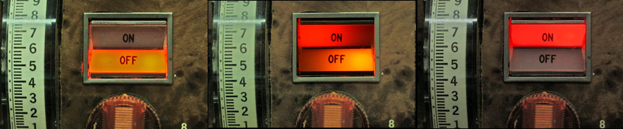
These indications give you a chance to make sure what will and won't "come on" when the bench is fully powered up (i.e. by turning the key switch to "start"). If you see that something will power up that you don't want - you have the chance to turn it off before it actually powers up. In the case of the "Controlled" outlet transformer - the switch also shows actual output state. If the electronic circuit breaker has activated - the indication will be the same as the middle one above - plus the "tripped" LED will be lit as well. Here is a short video of the process. Bench Demo (click here) First, the bench is put into standby (key switch to "ON") - and the switches show their state. At this time - the "Controlled" outlet is "OFF" - and will not power up with the bench. Then the switch for the "Controlled" outlet is pressed - setting the transformer control circuit "on"- to energize with the bench. The bench is then energized (key switch to "start"). The Controlled outlet transformer is now energized. There is an electric motor plugged into that outlet - but since the variable transformer is set to Zero Volts out - nothing happens. Then the transformer is turned up - until the electronic circuit breaker "trips". The switch lamps indicate the power has been removed - and the tripped LED also indicates that it is the sense circuit that has caused the control relay to drop out. The circuit is reset by turning the control switch off - then back on. Since the overload still exists - the circuit trips immediately. Changing the trip point select switch to 4A allows the circuit to remain energized at this point. Once enough voltage is applied to the motor - it begins to run - and the ammeter settles back to indicate the run current. Then the Trip point is set back to 1A - and of course the circuit trips immediately. Several attempts to "turn down" the transformer and reset it at the 1A setting are made until the current is again below 1A - and the circuit holds. Then the transformer is again raised until 1A is exceeded - and the circuit trips once more. The Controlled outlet transformer circuit is switched off - then the bench is shut down by turning the key switch to "OFF". |
||||
|
|
||||
 |
||||
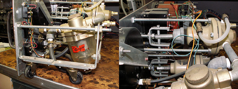
| The pneumatic "end" of the control panel. At this point - it's not used anymore - though I might use the vacuum part again in the future. Also - note the casters that make rolling the panel into and out of it's "home" slot a whole lot easier. The "drives" for the regulators are forks which allow the regulator shaft to screw into and out of the regulator body - while the knobs stay put on the front. Some of the modifications made to "convert" a pressure regulator into a vacuum regulator can be seen as well - since the regulator is working with vacuum - the "sense" and atmosphere sides of the diaphragm had to be reversed. The "back" of the diaphragm is now vented to atmosphere - while the "front" side is connected to "sense" the output. Since that side was vented before - the vent hole - and the adjuster shaft had to be sealed off. The vent was enlarged and tapped for the "sense pipe"- and the nose of the regulator body was turned and threaded so packing and a packing "nut" could be installed. A original pressure spring was replaced with a much less tension spring to allow more precise control (think of it as a 0 - 14psi regulator - just backwards!). | ||||
|
|
||||
 |
||||
|
||||
|
|
||||
| As noted - the panel controls an 0-30V 0-10A DC power supply. Most of the circuitry for the supply is mounted either on the panel (control variable resistors, meters, etc.) or on the panel's main circuit board. The transformer, bridge rectifier, etc. are mounted under the bench - while the series pass devices (LM-395) are mounted on the back panel - using it as a heat sink. I used to provide a link to the info on the supply - but National has redone their site several times - and the link breaks. So - here is their main page (hopefully this won't change anytime soon) National Semiconductor -- on the page is a search box - search for "LB-28" - and you'll have the design for that supply. | ||||
|
|
||||
| Modifications over the years: There have been few failures - the only major one - was most likely a lightning strike (several other items were damaged at the same time). The original 28VDC supply was replaced with a commercial unit. It is a "brute force" supply (i.e. weighs about 60 pounds) and the output voltage is "suggested" by taps. It's output was set high - and passed through the original series pass devices in/on the bench. Two things were added to the bench for safety reasons: The 28V supply has a reverse polarity diode just after the input fuse. This is to prevent the obvious mis-wiring; and also against AC mains should a mistake plugging in the "red and green" connectors. A fuse was also added in the AC input line - neither are shown on the schematics (I guess I should update them - sometime I'll get around toit.
As noted - had I known then what I know now - I'd leave the pneumatic section out - and leave more room for other toys... |
||||
|
|
||||
|
||||
|
|
||||
| Visitors: |